In our previous lesson, we established how to determine the basic allowable stress, , which represents the inherent strength of a pipe material under specific temperature conditions. However, this value assumes a flawless, homogenous material. We now need to account for the realities of pipe manufacturing, particularly the presence of longitudinal weld seams, which can influence the overall strength of the pipe.
This lesson addresses that very point by introducing the weld joint quality factor, . This crucial factor modifies the allowable stress to reflect the manufacturing method of the pipe and the level of quality control applied to its longitudinal weld. By the end of this lesson, you will be able to determine the correct value for any given pipe specification by using the tables within ASME B31.3, completing the set of primary parameters needed for pressure design calculations.
What is the Weld Joint Quality Factor ()?
The weld joint quality factor, often called the "longitudinal joint factor," is a de-rating factor applied to the allowable stress of a pipe. Its value ranges from 1.0 down to 0.60. A factor of 1.0 represents full confidence in the joint's ability to match the strength of the base metal, while a lower factor indicates a reduced level of confidence.
It is critical to understand that applies only to the longitudinal or spiral weld seam created during the pipe's manufacture. It has no bearing on the circumferential butt welds you would make in the field or shop to join pipe spools together.
The core purpose of this factor is to account for the quality and integrity of this manufacturing weld, which is directly tied to the Non-Destructive Examination (NDE) performed on it. A pipe with no weld (seamless) or a weld that has been 100% radiographed is considered to have the highest integrity, warranting a factor of 1.0. A pipe with a weld that has undergone less, or no, examination receives a lower factor.
This factor is a direct input into the wall thickness calculation formula found in para. 304.1.2 of the code:
As you can see, a lower value in the denominator increases the minimum required wall thickness, . This is how the code ensures a consistent margin of safety, demanding thicker walls for pipes with lower-confidence longitudinal seams.
The following short article provides a good introduction and poses a key question about the purpose of this factor.
API 570 Quiz (ASME 31.3 – Quality Factor of Weld-joint and Casting) – AMARINE
This article from AMARINE directly addresses the concept and purpose of the weld joint quality factor.
Please read the introductory section WELD JOINT QUALITY FACTORS and review Question 1. Note how the answer confirms that the factor is directly related to the NDE performed on the weld.
Finding the Basic Quality Factor: Table A-1B
The most straightforward way to find the basic quality factor is by looking at the pipe material specification itself. ASME B31.3 compiles these values in Table A-1B.
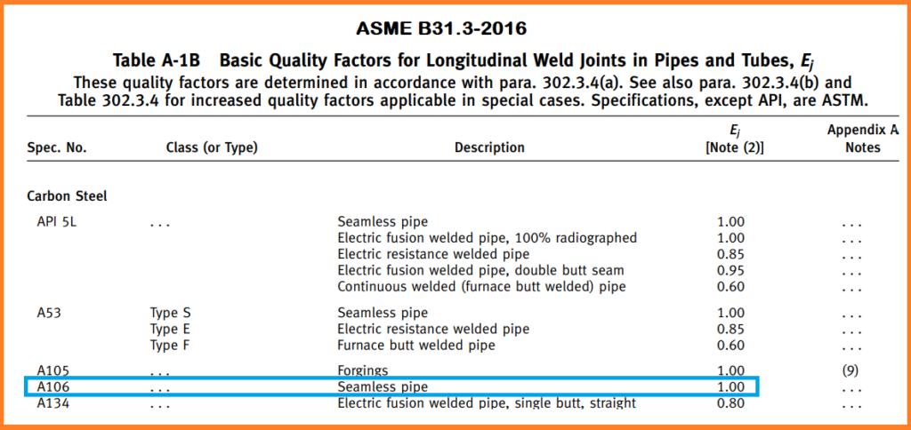
Let's examine this table:
- Seamless Pipe: Find the row for A106, a common seamless carbon steel pipe. As highlighted, its description is "Seamless pipe," and its is 1.00. This is the baseline, as there is no longitudinal weld.
- Electric Resistance Welded (ERW) Pipe: Look at the row for A53. You will see "Type E" listed, which stands for Electric resistance welded. The corresponding is 0.85.
- Furnace Butt Welded Pipe: Again under A53, you see "Type F" for Furnace butt welded. This process has the lowest quality factor, .
This table provides the default values based on the manufacturing standard. For seamless pipe, the story ends here; the factor is always 1.0. For welded pipe, however, there is often an opportunity to improve this factor.
The following video provides an excellent summary of this concept.
Calculate Piping Design Thickness based on ASME B31 3 on API 570 Piping Inspector Exam!
This clip from I4I Academy gives a clear, practical explanation of the quality factor, distinguishing between different pipe types.
Watch the section from the quality factor explanation. The instructor clearly explains that E_j applies to the long seam, that seamless pipe (like A106) gets a factor of 1.0, and that you must refer to Table A-1B for welded pipes.
Increasing the Quality Factor with Examination: Table 302.3.4
While Table A-1B gives the basic factor, Table 302.3.4 allows a designer to use a higher quality factor if supplementary NDE is performed on the longitudinal weld, beyond what the material specification requires. Given your background in welding and quality, this table directly translates inspection efforts into tangible design advantages.

Let's walk through a common scenario using this table. Consider an Electric Fusion Welded (EFW) pipe with a single butt weld seam (Item 3a in the table):
- Baseline: If you only perform the examination required by the pipe's manufacturing specification, the factor is 0.80.
- Spot Radiography: If you specify that the longitudinal seam must be additionally spot radiographed per the rules in B31.3, you can increase the factor to 0.90.
- 100% Radiography: If you go further and specify 100% radiography of the longitudinal seam, you earn the highest factor of 1.00, effectively making the welded pipe equivalent to a seamless pipe in the eyes of the pressure design calculation.
This presents a classic engineering trade-off: the cost of additional NDE versus the potential cost savings from using a thinner wall pipe. Note that not all weld types can be "upgraded." For example, the table shows no provision for increasing the factor for Electric Resistance Welded (ERW) pipe (Item 2).
The same video clip you just reviewed continues to explain this exact process.
Calculate Piping Design Thickness based on ASME B31 3 on API 570 Piping Inspector Exam!
This part of the video explains the practical application of Table 302.3.4.
Please continue watching from the discussion on increasing factors. The instructor explains how designers can choose to perform additional radiography to increase the joint factor for EFW pipes, allowing for a thinner wall design.
Worked Examples
Let's solidify this with a few practical examples.
Example 1: Standard ERW Pipe
- Question: A designer specifies ASTM A53, Type E pipe for a utility line. What is the correct weld joint quality factor, ?
- Solution: This is a direct lookup.
- Go to Table A-1B (Image: ASME B31.3 Table A-1B).
- Find the specification "A53" and "Type E".
- The corresponding is 0.85.
Example 2: Seamless Pipe
- Question: A critical process line is designed using ASTM A106, Grade B pipe. What is ?
- Solution:
- Go to Table A-1B.
- Find the specification "A106". The description is "Seamless pipe".
- The corresponding is 1.00.
Example 3: Upgrading a Welded Pipe
- Question: A project uses large-diameter API 5L pipe, manufactured with an electric fusion welded, double butt seam.
- a) What is the basic per Table A-1B?
- b) The designer needs to minimize weight and specifies that the longitudinal seam shall be 100% radiographed in accordance with B31.3. What is the new ?
- Solution:
- a) In Table A-1B, find "API 5L". One of the descriptions is "Electric fusion welded pipe, 100% radiographed", which has an of 1.00. Another is "Electric fusion welded pipe, double butt seam", with an of 0.95. The latter applies if only the standard API 5L examination is done.
- b) Now, consult Table 302.3.4 (Image: ASME B31.3 Table 302.3.4). Look at item 4, "API 5L electric fusion welded...". The row for "Additionally 100% radiographed" gives a factor of 1.00. The designer's specification allows the use of this higher value.
Conclusion
You have now integrated a critical manufacturing and quality control parameter directly into the design process. This factor ensures that the assumed strength of the material is appropriately adjusted for the reality of its production method.
Here are the key takeaways from this lesson:
- The weld joint quality factor () is a de-rating factor applied to the allowable stress to account for the integrity of a pipe's longitudinal manufacturing seam.
- A seamless pipe always has an of 1.0.
- The basic for welded pipes is found in Table A-1B based on the material specification.
- The for certain welded pipes (like EFW) can be increased, up to a maximum of 1.0, by performing supplementary NDE as defined in Table 302.3.4.
- A lower requires a greater calculated wall thickness to maintain the system's safety margin.
We have now covered the primary factors— and —that determine the strength basis for welded and seamless wrought pipe. However, piping systems also include cast components like valve bodies, pump casings, and some fittings. These have their own manufacturing considerations.
In the next lesson, we will examine the casting quality factor (), a parallel concept that addresses the inherent quality of cast materials.