Hello! Welcome to our next lesson in the Advanced LAN Switching module.
In our previous lesson, we analyzed the mechanics of 802.1Q trunking, focusing on how frame tagging allows multiple VLANs to traverse a single link. We also noted that the 802.1Q tag includes a 3-bit Priority Code Point (PCP) field, which is used for Quality of Service (QoS)—a perfect lead-in to today's topic.
This lesson directly addresses the learning outcome: Configure and verify voice VLANs to support QoS for IP telephony. We'll explore a special type of switch port configuration that seems to break the rules of a standard access port, all to ensure that delay-sensitive voice traffic gets the priority it needs on a converged network. Given your work as a solutions engineer, understanding how to guarantee service quality for real-time applications like voice is a critical, practical skill.
1. The Need for Voice VLANs
In modern enterprise networks, data, voice, and video traffic all share the same infrastructure. While this is efficient, it creates a problem: what happens when a large file download competes for bandwidth with a CEO's conference call? The file download can tolerate a bit of delay, but the voice call will quickly become choppy and unusable.
To solve this, we must separate and prioritize traffic. The first step is to place voice traffic into its own dedicated VLAN, known as a voice VLAN.
IP phones are often deployed in a "daisy-chain" fashion, where a user's PC connects to a port on the phone, and the phone connects to a single port on the switch. This saves on cabling and switch ports but means both voice and data traffic must traverse the same link.
Free CCNA | QoS (Part 1) | Day 46 | CCNA 200-301 Complete Course
To start, let's watch a segment from Jeremy's IT Lab that introduces this physical topology and the concept of separating voice and data traffic into different VLANs.
Watch from 01:16 to 04:53. Pay attention to the explanation of the IP phone's internal 3-port switch and how a voice VLAN architecture allows a single switch port to support both a PC and a phone.
As the video explained, the IP phone essentially acts as a mini-switch. This setup leads to a unique traffic flow:
- Data Traffic: Frames from the PC pass through the phone to the switch. These are standard, untagged Ethernet frames.
- Voice Traffic: Frames generated by the IP phone itself are tagged with the voice VLAN ID before being sent to the switch.

2. The "Multi-VLAN Access Port"
This architecture requires a special switch port configuration. Although it carries traffic for two different VLANs (one tagged, one untagged), the port is not a trunk port. It's configured as an access port with an additional command to specify the voice VLAN.
The configuration looks like this:
switchport mode accessswitchport access vlan 10(This is the data VLAN for the PC)switchport voice vlan 50(This is the voice VLAN for the phone)
When configured this way, the switch port operates as follows:
- It accepts untagged frames and places them into the access VLAN (VLAN 10).
- It accepts frames tagged with the voice VLAN ID (VLAN 50) and places them into the voice VLAN.
- The switch uses Cisco Discovery Protocol (CDP) to inform the IP phone which VLAN ID it should use for tagging its voice traffic.
Free CCNA | QoS (Part 1) | Day 46 | CCNA 200-301 Complete Course
Let's continue with Jeremy's IT Lab to see this configuration in action and confirm the port's operational state. This is a key concept, as it's a common point of confusion.
Watch from 04:53 to 07:26. Note how the show interfaces switchport command confirms the port is in 'static access' mode, even though it handles two VLANs.
3. From Separation to Prioritization: Quality of Service (QoS)
Simply separating voice traffic into its own VLAN isn't enough to guarantee call quality. We also need to instruct the network hardware to give this traffic preferential treatment. This is where Quality of Service (QoS) comes in.
Voice traffic is highly sensitive to three main factors:
- Delay: The time it takes for a packet to travel from source to destination. High delay makes a conversation unnatural. (Recommended: < 150 ms one-way)
- Jitter: The variation in delay between packets. High jitter results in choppy, distorted audio. (Recommended: < 30 ms)
- Loss: The percentage of packets that are dropped and never arrive. Even small amounts of packet loss can degrade call quality. (Recommended: < 1%)
Free CCNA | QoS (Part 1) | Day 46 | CCNA 200-301 Complete Course
This short segment explains why these characteristics are so damaging to voice traffic and why QoS is essential in a converged network.
Watch from 14:31 to 19:36 to understand the specific performance requirements for voice traffic.
To meet these strict requirements, we need a way to mark voice packets as "important" and configure our switches to act on those markings.
4. Marking and Trusting Voice Traffic
Cisco IP phones automatically mark the traffic they generate to signal its priority. They use two primary methods:
- Layer 2 Marking (CoS): The phone sets the 3-bit Priority Code Point (PCP) field in the 802.1Q tag to a specific value. This is known as the Class of Service (CoS).
- Layer 3 Marking (DSCP): The phone sets the 6-bit Differentiated Services Code Point (DSCP) field in the IP header.
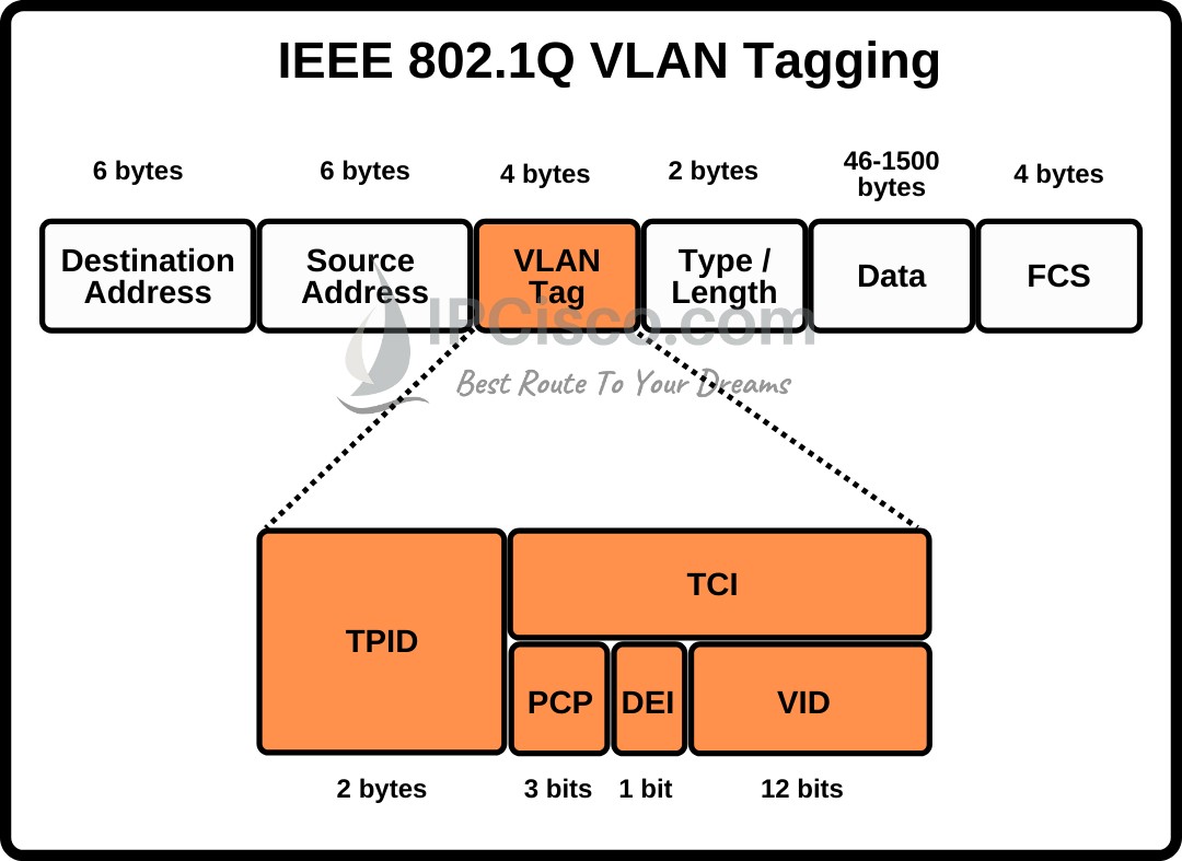
The switch, however, won't act on these markings unless it's configured to trust them. This creates a "trust boundary." We trust the markings from a corporate IP phone, but we might not trust markings from a user's PC, as they could be maliciously altered to give their data traffic unfair priority.
To understand these markings in detail, let's turn to Kevin Wallace's "QoS Deep Dive." This is a more advanced discussion suitable for the CCNP level that explains the math behind CoS and DSCP and their relationship.
Watch from 24:34 to 32:20. Focus on the explanation of the 3-bit CoS value and the key fact that Cisco IP phones default to a CoS value of 5 for voice traffic. This is the value our switch needs to trust.
5. Configuration and Verification
Now, let's put all the pieces together. To properly configure a switch port for a Cisco IP phone and ensure QoS, we need to perform these steps.
This official Cisco documentation provides the specific commands needed to configure a voice VLAN and, critically, to establish the trust model for QoS. We'll use this as our guide for the configuration steps.
First, read the 'Information About Voice VLAN' section to reinforce the core concepts. Then, carefully review the 'SUMMARY STEPS' and 'DETAILED STEPS' under the 'Configuring Cisco IP Phone Voice Traffic' section. This shows the full command sequence.
Here is a summary of a complete manual configuration:
-
Enable QoS Globally: This is a prerequisite on many Catalyst switch platforms.
Switch(config)# mls qos -
Configure the Interface:
Switch(config)# interface GigabitEthernet1/0/1
Switch(config-if)# switchport mode access
Switch(config-if)# switchport access vlan 100      ! Data VLAN
Switch(config-if)# switchport voice vlan 110      ! Voice VLAN
Switch(config-if)# mls qos trust cos              ! Trust the Layer 2 CoS marking
Switch(config-if)# spanning-tree portfast         ! Recommended, though often enabled automatically
Note: On newer platforms, you might see
trust device cisco-phone. This command provides conditional trust, instructing the port to only trust markings if CDP detects that the connected device is a Cisco IP phone. -
Verification:
The primary command to verify your configuration isshow interfaces <interface-id> switchport.Switch# show interfaces gigabitethernet1/0/1 switchport Name: Gi1/0/1 Switchport: Enabled Administrative Mode: static access Operational Mode: static access Administrative Trunking Encapsulation: dot1q Operational Trunking Encapsulation: native Negotiation of Trunking: Off Access Mode VLAN: 100 (Data) Trunking Native Mode VLAN: 1 (default) Voice VLAN: 110 (Voice) [...]Notice that the operational mode is
static access, and both the Access VLAN and Voice VLAN are listed.
Test your understanding!
A network administrator needs to connect a new Cisco IP phone and an accompanying user PC to port FastEthernet0/24. The user's data traffic should be in VLAN 20, and voice traffic should be in VLAN 30. Write the complete interface configuration to enable this, ensuring that the switch prioritizes the voice traffic based on the phone's markings.
Show answer
First, QoS must be enabled globally if it isn't already.
Switch(config)# mls qos
Then, the interface configuration is as follows:
Switch(config)# interface FastEthernet0/24
Switch(config-if)# switchport mode access
Switch(config-if)# switchport access vlan 20
Switch(config-if)# switchport voice vlan 30
Switch(config-if)# mls qos trust cos
Switch(config-if)# end
This configuration correctly places untagged data traffic in VLAN 20, assigns tagged voice traffic to VLAN 30, and instructs the switch to trust the CoS markings in the 802.1Q tag sent by the phone.
6. AutoQoS: The Simplified Approach
Configuring QoS can become very complex. To simplify deployment for common scenarios like VoIP, Cisco created AutoQoS. This is a set of macros that automatically generates and applies a best-practice QoS configuration based on the type of device connected to the port.
Let's return to Kevin Wallace's demo, where he shows how a single AutoQoS command can generate a very comprehensive configuration for an IP phone.
Watch from 1:34:09 to 1:37:27. Observe the command auto qos voip cisco-phone and the extensive configuration it creates, including trust settings and queueing parameters.
While AutoQoS is a powerful tool for rapid deployment, it's essential for a CCNP candidate to understand the manual steps it automates. This knowledge is crucial for customization and advanced troubleshooting when the automatic configuration isn't sufficient.
Conclusion
In this lesson, we bridged the gap between basic VLAN switching and Quality of Service. We saw how the special voice VLAN configuration allows a single access port to securely handle both untagged data and tagged voice traffic, enabling the prioritization that real-time applications demand.
Key Takeaways:
- Voice VLANs are used to segregate IP telephony traffic from data traffic for security and QoS management.
- A switch port connected to an IP phone and a PC operates in access mode but is configured with both a data VLAN (
switchport access vlan) and a voice VLAN (switchport voice vlan). - The switch receives untagged data frames for the access VLAN and tagged voice frames for the voice VLAN.
- To enable prioritization, the switch must be configured to trust the Layer 2 CoS markings sent by the IP phone using the
mls qos trust coscommand. - AutoQoS provides a simplified macro (
auto qos voip) to apply a robust, best-practice QoS configuration to a port.
Preview of the Next Lesson:
We will continue our exploration of advanced VLAN technologies by looking at another method of Layer 2 segmentation. In the next lesson, we will learn how to configure and verify private VLANs to provide Layer 2 isolation between hosts within the same subnet, a powerful tool for security in multi-tenant environments.