Hello! Let's continue our exploration of advanced Spanning Tree Protocol concepts.
In our last lesson, we configured Rapid PVST+ and observed its fast convergence mechanisms. We noted that while it's a significant improvement over legacy STP, its "per-VLAN" nature can create a scalability challenge in large enterprise networks with hundreds of VLANs, leading to high CPU utilization on switches.
This lesson directly addresses that challenge. We will analyze the operation and configuration of Multiple Spanning Tree Protocol (MST), the IEEE 802.1s standard. MST is designed for efficiency and scalability by allowing you to map multiple VLANs to a single spanning tree instance, dramatically reducing the number of instances a switch must process while still enabling robust load balancing.
1. The Case for MST: Efficiency and Scalability
The fundamental principle of MST is the decoupling of VLANs from spanning tree instances. Instead of the one-to-one relationship found in PVST+ and Rapid PVST+, MST introduces a many-to-one relationship.
To start, let's establish why this is so beneficial in a large Layer 2 domain.
Understand the Multiple Spanning Tree Protocol (802.1s)
This official Cisco documentation clearly explains the problem MST solves. Pay close attention to the diagrams comparing PVST+, standard 802.1q, and MST in a network with 1000 VLANs.
Please read the section 'Where to Use MST'. This section demonstrates why running 1000 PVST+ instances is inefficient when you only need two distinct logical topologies for load balancing.
As the document illustrated, if your goal is to load-balance traffic across two distribution switches, you only need two unique spanning tree topologies. Running an instance for every single VLAN is redundant and resource-intensive. MST allows you to create just two MST Instances (MSTIs) and map the appropriate VLANs to each one.
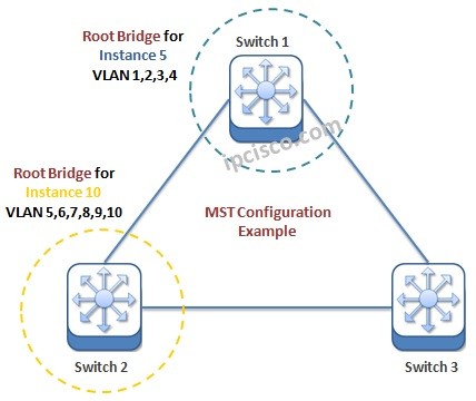
2. MST Building Blocks: Instances and Regions
To make this "many-to-one" mapping work, MST introduces two key concepts: MST Instances and MST Regions.
MST Instances (MSTIs)
An MSTI is a single spanning tree instance to which multiple VLANs can be mapped. Cisco switches support up to 65 MSTIs.
- MSTIs 1-4094: These are the instances you create for your load-balancing topologies.
- MSTI 0 (Instance 0): This is a special, mandatory instance called the Internal Spanning Tree (IST). It runs in every MST network by default, and all VLANs are mapped to it until you reassign them. As we'll see later, the IST plays a crucial role in how MST interacts with other regions and non-MST networks. All BPDUs in an MST network are technically sent for Instance 0, with the information for all other MSTIs encapsulated within them.
MST Regions
For this system to function, a group of switches must agree on which VLANs map to which instances. An MST Region is a group of interconnected switches that share an identical MST configuration. A switch's membership in a region is determined by three attributes, which must match exactly on all switches in that region:
- Configuration Name: A 32-character string that you define.
- Revision Number: A number from 0 to 65535 that you can use for version control.
- VLAN-to-Instance Mapping: A table that lists which VLANs are mapped to which MSTI. The switch doesn't send this entire table in BPDUs; instead, it sends a computed hash (digest) of the table.
If a switch receives a BPDU from a neighbor with a different name, revision number, or mapping digest, it considers that neighbor to be in a different region.
Let's watch a video that breaks down these core concepts and walks through the initial configuration.
CCNP ENCOR // MSTP Basics // ENCOR 350-401 Complete Course
This video from Jeremy's IT Lab provides an excellent introduction to the fundamentals of MST, including the configuration process and the role of Instance 0.
Please watch from the beginning to 12:02. This segment covers: The advantages of MST over Rapid PVST+. The role of the Internal Spanning Tree (IST / MSTI0). The step-by-step process for enabling MST, creating new instances, and mapping VLANs.
3. MST Configuration and Verification
As you saw in the video, configuring MST involves a few distinct steps. Let's formalize them using Cisco's official configuration guide.
Configuring Multiple Spanning-Tree Protocol
This configuration guide provides the precise commands for setting up an MST region. We'll use this as our command reference.
Review the table under the section 'Specifying the Multiple Spanning Tree Region Configuration and Enabling Multiple Spanning Tree Protocol'. This shows the sequence of commands to enter MST configuration mode, define the region, map VLANs, and then enable MST globally.
To summarize the configuration workflow:
- Enter MST Configuration Mode:
Switch(config)# spanning-tree mst configuration - Define Region Attributes: While in
config-mstmode, you define the three critical parameters.Switch(config-mst)# name REGION-A Switch(config-mst)# revision 1 Switch(config-mst)# instance 1 vlan 10,20,30 Switch(config-mst)# instance 2 vlan 40,50,60 - Apply and Exit: The changes only take effect when you exit
config-mstmode.Switch(config-mst)# exit - Enable MST Globally:
Switch(config)# spanning-tree mode mst - Configure Root Bridges: After enabling MST, you configure the root and backup root bridges for each instance, just as you would for PVST+.
Switch(config)# spanning-tree mst 1 root primary
Switch(config)# spanning-tree mst 2 root secondary
Once configured, you can verify your work using these commands:
show spanning-tree mst configuration: Confirms the region name, revision, and VLAN-to-instance mappings.show spanning-tree mst <instance-id>: Shows the topology for a specific instance, including the root bridge and port roles.
Test your understanding!
You need to make a switch the root bridge for MST instance 5. Which configuration mode must you be in to issue the spanning-tree mst 5 priority 4096 command?
Show answer
You must be in global configuration mode (config#). Commands that affect the spanning tree topology, such as setting priority or using the root primary macro, are done in global config. The special mst configuration mode (config-mst#) is only for defining the region attributes (name, revision, and VLAN-to-instance mapping).
4. Advanced Analysis: Multi-Region Operation
In a simple network, you might have just one MST region. However, in large or complex environments, or when merging networks, you may have multiple regions. Understanding how they interact is crucial for a CCNP-level analysis of MST.
When multiple regions exist, MST creates an overarching loop-free topology using these components:
- Common Spanning Tree (CST): A single spanning tree that connects all MST regions and any legacy (non-MST) switches. From the CST's perspective, each entire MST region looks like a single virtual switch.
- Common and Internal Spanning Tree (CIST): This is the complete spanning tree for the entire network. It's the sum of the Internal Spanning Trees (ISTs) within each region plus the Common Spanning Tree (CST) that connects them.
- CIST Root: The single switch with the best bridge ID in the entire network (across all regions) becomes the CIST Root. This switch is the ultimate root for the entire CIST.
- CIST Regional Root: For any region that does not contain the CIST Root, one switch on the boundary of that region is elected as the CIST Regional Root. This switch has the lowest-cost path to the CIST Root. It then acts as the root bridge for its own region's IST (Instance 0).
- Master Port: On the CIST Regional Root, the port that serves as its root port towards the CIST Root is given the special role of Master Port. This port acts as the gateway for traffic from other MSTIs in the region to reach other regions.
These concepts can be complex. The following video provides a detailed, visual explanation of how these pieces fit together.
CCNP ENCOR // MSTP Regions // ENCOR 350-401 Complete Course
Let's dive deeper into how multiple regions interconnect. This video from Jeremy's IT Lab is dedicated to explaining the CIST, CIST Regional Root, and the Master port.
Please watch from the beginning to 27:39. This is a comprehensive look at multi-region MST. Focus on: How the MCID (name, revision, digest) defines a region. The relationship between the IST, CST, and CIST. How the CIST Root and CIST Regional Root are elected. The role of the Master Port in connecting MSTIs across regions.
This deep dive shows that while MST simplifies the workload on switch CPUs, its underlying architecture is sophisticated, ensuring a loop-free topology both within and between regions.
Conclusion
In this lesson, we analyzed the operation and configuration of MST. We started by identifying the scalability problem with per-VLAN protocols and saw how MST solves it by mapping many VLANs to fewer instances. We then broke down the essential components of MST—Instances and Regions—and walked through the configuration process. Finally, we took a deep dive into the architecture of multi-region MST networks, exploring how the CIST, regional roots, and master ports work together to build a coherent, loop-free topology.
Key Takeaways:
- MST (802.1s) solves the scalability issues of (Rapid) PVST+ by mapping multiple VLANs to a single MST Instance (MSTI).
- A group of switches with an identical configuration (name, revision number, and VLAN-to-instance mapping) form an MST Region.
- Instance 0 (IST) is a special instance that runs within each region and is responsible for exchanging BPDUs and interacting with the outside world.
- In a multi-region network, a single CIST provides a loop-free path across the entire topology. The root of this is the CIST Root. Regions without the CIST Root elect a CIST Regional Root to provide connectivity.
- Configuration requires defining region attributes in
spanning-tree mst configurationmode and enabling MST globally withspanning-tree mode mst.
Preview of the Next Lesson:
Now that we have a solid understanding of the different flavors of Spanning Tree Protocol (RSTP and MSTP), our next step is to secure our Layer 2 topology. In the next lesson, we will configure and verify STP protection features including BPDU Guard, Root Guard, and Loop Guard to prevent common issues caused by misconfigurations or unauthorized device connections.