Hello! Welcome to your next lesson in the "Network Virtualization" module.
In our last session, you analyzed the components of Cisco's SD-WAN solution, understanding how vManage, vSmart, vBond, and WAN Edges create a software-defined architecture for the wide area network. Today, we shift our focus from the WAN to the campus LAN and explore its software-defined counterpart: Cisco SD-Access.
The learning outcome for this lesson is to analyze the components of a Cisco SD-Access architecture (underlay, overlay, fabric control plane).
You'll find that many of the core principles—separating the control plane from the data plane, using an overlay to virtualize the network, and having a centralized management system—are directly parallel to what you learned about SD-WAN. This lesson will equip you to understand the fundamental building blocks of this modern campus architecture.
From Three Tiers to a Fabric
Traditional campus networks are built on a hierarchical three-tier model (core, distribution, access). While robust, this design can be rigid and complex, especially with the need to stretch Layer 2 domains for endpoint mobility, which often leads to reliance on Spanning Tree Protocol.
SD-Access replaces this model with a fabric, a more flexible and intelligent architecture composed of two primary layers: an underlay and an overlay.
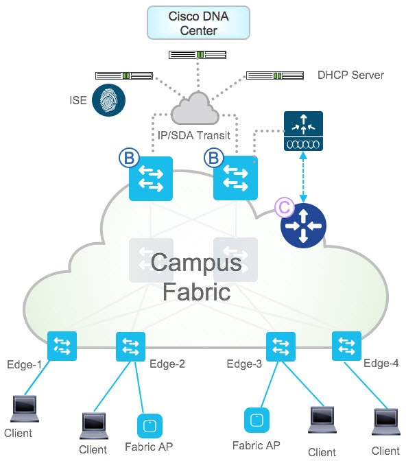
Let's start by defining the underlay and overlay, which are foundational to understanding the entire architecture.
Cisco Software-Defined Access Solution Design Guide
The official 'Cisco Software-Defined Access Solution Design Guide' provides clear, authoritative definitions for these concepts. Understanding this distinction is the first step to grasping the architecture.
Please read the sections titled 'Underlay network' and 'Overlay network' within the 'SD-Access architecture network components' chapter. Focus on how the underlay provides physical transport and the overlay provides logical virtualization.
The Underlay Network: The Physical Foundation
The underlay is the physical network of switches and routers. Its sole purpose is to provide IP reachability between all the devices that make up the fabric. Think of it as the road system upon which the logical overlay network will be built.
Key characteristics and design requirements for the underlay include:
- Layer 3 Routed Access: Unlike traditional designs that use Layer 2 links from distribution to access, an SD-Access underlay uses Layer 3 point-to-point links everywhere. This eliminates blocked ports from Spanning Tree and provides fast, predictable convergence using standard routing protocol mechanisms like ECMP (Equal-Cost Multi-Path).
- Interior Gateway Protocol (IGP): An IGP (like OSPF, EIGRP, or IS-IS) is run on all underlay devices to advertise reachability for their loopback interfaces. Cisco's LAN Automation feature uses IS-IS by default, but manual deployments with OSPF are very common in the enterprise.
- Increased MTU: The overlay encapsulation (VXLAN) adds 50 bytes of overhead to each packet. Therefore, all interfaces in the underlay must be configured with a larger MTU (typically 9100 bytes is recommended) to avoid fragmentation.
ENCOR - SD-Access Architecture
This video from KishSquared provides an excellent, practical walkthrough of SD-Access architecture. This first segment clearly explains the underlay and how it differs from a traditional network.
Watch from 46:40 to 52:15. Pay attention to the discussion on why a Layer 3 underlay is preferred, the role of the IGP, and the critical importance of increasing the MTU.
The Overlay Network and its Operational Planes
The overlay is the virtual network, or fabric, that is tunneled on top of the underlay. This is where user traffic flows and policies are enforced. The overlay is defined by three key operational planes, each powered by a specific protocol.
Cisco Software-Defined Access Solution Design Guide
Let's turn back to the 'Cisco Software-Defined Access Solution Design Guide' for a breakdown of the three key planes that make SD-Access work.
Read the entire 'SD-Access operational planes' section. This is a critical part of the lesson. Focus on associating each plane (control, data, policy) with its corresponding protocol (LISP, VXLAN, TrustSec).
Let's summarize those key planes:
- Data Plane (VXLAN): Virtual Extensible LAN is the encapsulation protocol that creates the overlay tunnels. It takes the original Ethernet frame from an endpoint and wraps it in a new set of IP and UDP headers. This allows Layer 2 segments to be "stretched" across the Layer 3 underlay.
- Control Plane (LISP): The Locator/ID Separation Protocol is the "brains" of the fabric. It decouples a device's identity (who it is) from its location (where it is).
- Endpoint ID (EID): The IP or MAC address of an endpoint. This doesn't change as the user moves.
- Routing Locator (RLOC): The IP address of the underlay switch (the fabric edge node) that the endpoint is currently connected to. This is typically a loopback address.
LISP maintains a dynamic database that maps EIDs to RLOCs, telling the fabric how to find any endpoint at any time. This is conceptually similar to how OMP works in SD-WAN.
- Policy Plane (Cisco TrustSec): This plane handles security and segmentation using Scalable Group Tags (SGTs). When a user connects, they are assigned a tag (e.g., "Employee," "IoT_Device") by the Cisco Identity Services Engine (ISE). This tag is carried in the VXLAN header and used to enforce access policies throughout the fabric, regardless of the device's IP address or location.
SD-Access Components: The Fabric Roles
Now that we understand the underlay, overlay, and control plane, let's analyze the specific roles that network devices play within the fabric. A single physical device (like a Catalyst 9000 switch) is assigned one or more of these logical roles.
ENCOR - SD-Access Architecture
This next, longer segment from the KishSquared video is the core of our lesson. It explains each physical role in detail, showing how a traditional network topology is transformed into an SD-Access fabric.
Watch from 8:42 to 28:56, then jump to 59:06 to 1:05:56. This combined segment covers: The four main device roles: Fabric Edge, Border, Control Plane, and Wireless LAN Controller. A clear explanation of how LISP provides control plane separation. A practical example of mapping a traditional 3-tier design to these new SD-Access roles.
Drawing from the video and official documentation, let's solidify the function of each component.
1. Control Plane Node
- Function: This is a dedicated device (or a role running on a Border Node) that runs the LISP Map-Server and Map-Resolver. It maintains the central EID-to-RLOC mapping database for the entire fabric site. When an edge node needs to find an endpoint, it queries the control plane node.
- Analogy: Think of it as the fabric's DNS server. It resolves an endpoint's identity (EID) to its current location (RLOC).
2. Fabric Edge Node
- Function: This is an access layer switch where endpoints (laptops, phones, APs) connect.
- It registers the EIDs of its connected clients with the Control Plane Node.
- It performs VXLAN encapsulation for traffic entering the fabric and decapsulation for traffic leaving the fabric toward an endpoint.
- It functions as the Anycast Layer 3 gateway for all connected endpoints.
- Analogy: The on-ramp and off-ramp to the fabric highway.
3. Fabric Border Node
- Function: This is the gateway that connects the SD-Access fabric to any external network, such as the WAN, the data center, or a traditional part of the campus.
- It advertises the fabric's EID subnets to the outside world (usually via BGP).
- It translates policies between the fabric (SGTs) and the external network.
- It acts as the default gateway for the fabric; if an edge node doesn't have a specific RLOC for a destination, it sends the traffic to the border node.
- Analogy: The international airport connecting the fabric to the rest of the world.
4. Intermediate Node
- Function: Any router or switch in the underlay that is not an edge, border, or control plane node. Its only job is to route IP traffic between the RLOCs. It is not fabric-aware and does not perform any encapsulation or LISP functions.
- Analogy: A simple transit stop on the road system that just passes traffic through.
Test your understanding!
A user moves their laptop from a desk connected to Edge-Node-1 to a conference room connected to Edge-Node-2. The user's IP address remains the same. Describe the high-level process and identify the key fabric components involved in ensuring their network connectivity is seamlessly maintained.
Show answer
- When the laptop connects to
Edge-Node-2, the switch detects the new device. Edge-Node-2sends a LISP map-register message to the Control Plane Node, updating the EID-to-RLOC database to map the user's IP address (EID) to the new location (Edge-Node-2's RLOC).- When another device in the fabric wants to send traffic to this user, its local edge node will query the Control Plane Node.
- The Control Plane Node will reply with the new mapping, informing the source edge node to encapsulate the traffic in a VXLAN tunnel destined for
Edge-Node-2.
Management and Policy Orchestration
Finally, it's important to recognize the two external components that manage the entire solution:
- Cisco Catalyst Center (formerly DNA Center): This is the centralized management platform, analogous to vManage in SD-WAN. It provides the GUI and REST APIs to design, provision, and monitor the entire fabric. As a solutions engineer, you'd appreciate that this is the primary interface for automation.
- Cisco Identity Services Engine (ISE): This is the policy engine. It integrates with Catalyst Center to manage user and device identity, assign SGTs, and define the access control policies for micro-segmentation.
Let's watch a brief, official overview of how Catalyst Center and ISE fit into the architecture.
Watch from 3:48 to 6:30. This provides a concise summary of the three pillars of SD-Access (automation, segmentation, policy) and clarifies the roles of Catalyst Center and ISE as the controller and policy-helper, respectively.
Conclusion
Today we've deconstructed the Cisco SD-Access architecture into its fundamental components. By moving from a rigid, hierarchical design to a flexible fabric, SD-Access provides the automation, segmentation, and scalability required for modern campus networks.
Key Takeaways:
- Underlay: A Layer 3 routed network providing IP transport between all fabric devices (RLOCs).
- Overlay: A virtual network tunneled over the underlay using VXLAN for the data plane.
- Fabric Control Plane: Run by LISP, which maps endpoint identities (EIDs) to their network locations (RLOCs).
- Key Fabric Roles:
- Control Plane Node: The LISP database/resolver.
- Edge Node: Connects endpoints and performs encapsulation/decapsulation.
- Border Node: The gateway to external networks.
- Management & Policy: Orchestrated by Cisco Catalyst Center and enforced by Cisco ISE.
Preview of the Next Lesson:
In this lesson, we introduced LISP and VXLAN as the key protocols of the fabric. In our next session, Describe the role of LISP and VXLAN as key protocols in the SD-Access fabric, we will take a deeper dive into the mechanics of these two technologies to understand exactly how they enable the magic of the overlay.