Welcome to the next lesson in our database design course. In our previous session, we focused on identifying foreign keys and understanding how they act as the "glue" that connects different tables. We saw that a foreign key in one table references a primary key in another, creating a structural link.
Today, we're going to build directly on that idea by formally defining what these links are. This lesson focuses on a core concept in data modeling: the relationship. We will explore what a relationship represents in a database context, how it describes the interaction between different entities, and how it is visually represented. Understanding this is the first step toward analyzing and mapping the complex connections within any business system.
1. Defining a Relationship
At its heart, a relationship is simply an association or interaction between entities. In the last lesson, we saw how the CustomerID foreign key in an ORDERS table creates a link to the CUSTOMERS table. That link represents a real-world relationship: a customer places an order.
Let's start with two short videos that provide a clear and concise definition of this concept.
Concept of Relationships in ER Diagram
First, watch this brief video from Neso Academy for a formal definition of a relationship.
Watch the entire clip, from the beginning to the end. Notice how it defines a relationship as a connection between two or more entities using the example "Teacher teaches Student."
Entity Relationship Diagram (ERD) Training Video
Next, let's watch a more conversational explanation that builds on this idea.
Please watch the section from this clip. It emphasizes that a relationship describes how entities interact and is often represented by a verb, like "a student has a phone number."
As both videos highlight, a relationship isn't just an abstract link; it represents a specific action or association. This brings us to a helpful analogy.
2. Entities as Nouns, Relationships as Verbs
A great way to think about the components of a database model is to compare them to parts of a sentence:
- Entities are like nouns: they represent people, places, things, or concepts (e.g.,
STUDENT,COURSE). - Attributes are like adjectives: they describe the properties of the nouns (e.g., a student's
FirstName, a course'sTitle). - Relationships are like verbs: they describe the action or association that connects the nouns (e.g., a
STUDENTenrolls in aCOURSE).
This "noun-verb" structure is fundamental to translating business requirements into a database design. When analyzing a scenario, you'll find yourself identifying the key nouns (entities) and the verbs that connect them (relationships).
The following reading from an IBM article explains this clearly.
What is an Entity Relationship Diagram?
This article provides a concise overview of ERD components. We will focus on the section defining relationships.
Please read the section titled "Relationships." Pay attention to the analogy: "If entities are nouns, and attributes are adjectives, then relationships are verbs."
3. Visualizing Relationships in an ERD
In an Entity-Relationship Diagram (ERD), each component has a standard symbol. While entities are shown as rectangles and attributes as ovals, relationships are typically represented by a diamond shape placed on the line connecting the entities.

Let's look at a more concrete example. The diagram below shows two entities, Student and Course. The diamond in the middle, labeled "Joins," represents the relationship between them.
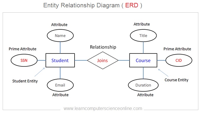
This visual format makes the structure of the database easy to understand at a glance. You can immediately see the main components (Student, Course) and how they are associated with each other.
To bring these ideas together, let's read one final piece that defines entities and relationships in the context of an overall data model.
The Entity Relationship Data Model
This chapter excerpt introduces the ER model by defining its two core concepts: entities and relationships.
Read the first three paragraphs of the chapter, starting from "The entity relationship (ER) data model..." and ending with "...teaches (relationship) the Database Systems course (entity)." This will reinforce the definitions we've covered today.
Conclusion
In this lesson, we formally defined what a relationship is in the context of database design. We moved from the physical implementation (foreign keys) to the logical concept that those keys represent.
Key Takeaways:
- A relationship is an association or interaction between two or more entities.
- Relationships can be thought of as the verbs that connect the nouns (entities) in a system (e.g., a
DOCTORtreats aPATIENT). - These connections are the "glue" of the database, implemented physically using foreign keys.
- In an ERD, a relationship is visually represented by a diamond shape connecting the related entities.
Now that we have a solid definition of what a relationship is, our next step will be to learn how to actively identify these relationships from a business scenario description. Following that, we will learn how to classify them by their type—one-to-one, one-to-many, or many-to-many—which will be crucial for drawing accurate ERDs.