Hello! Welcome to the fourth lesson in our journey into analog circuits.
In our previous lessons, we've focused on the relationships between voltage, current, resistance, and power within simple, single-path circuits. We established Ohm's Law () as our primary tool. However, most real-world circuits, from a simple stereo to the complex hardware you're interested in, involve multiple paths for current to flow.
Today, we'll learn our first fundamental law for analyzing these more complex networks: Kirchhoff's Current Law (KCL). This law provides a simple but powerful rule for what happens to current at a junction point. Your goal for this lesson is to be able to apply KCL to analyze current flow at circuit nodes. This is a critical building block for the more sophisticated analysis techniques we'll encounter later.
1. The Conservation of Charge at a Node
The entire principle behind KCL is one of the most fundamental laws of physics: the conservation of charge. Since current is the flow of charge, it means that charge cannot be created or destroyed at any point in a circuit. It also can't just pile up indefinitely at a junction.
A junction where two or more components meet is called a node. KCL simply states that the total amount of current flowing into a node must be equal to the total amount of current flowing out of it.

Let's watch a short video that introduces this concept from first principles.
Kirchhoff's current law | Circuit analysis | Electrical engineering | Khan Academy
This clip from Khan Academy provides a clear, intuitive explanation of what a node is and how the idea of charge conservation leads directly to Kirchhoff's Current Law.
Watch the segment from 00:24 to 02:28. Focus on the core argument: because charge doesn't accumulate at a node, whatever current enters must leave.
2. The Two Forms of KCL
As the video explained, we can express KCL in two equivalent ways.
Form 1: Sum of Currents In = Sum of Currents Out
This is the most intuitive form. For the node shown in the image above, this would be written as:
In general, for any node:
Form 2: The Algebraic Sum of Currents is Zero
This form is more common in formal analysis and is the basis for computer-aided circuit simulation. To use it, we must first establish a sign convention. A widely used convention is:
- Currents entering a node are considered positive (+).
- Currents leaving a node are considered negative (-).
With this convention, the "algebraic sum" of all currents at a node must be zero. For the same node, this would be:
which you can see is algebraically identical to the first form. In general:
Let's watch one more short clip to solidify this formal definition and the sign convention.
Neso Academy provides a slightly more formal definition and clearly states the sign convention. It also directly links KCL to the law of conservation of charge.
Watch the video from the beginning to 07:05. Pay close attention to how the sign convention is applied to form the KCL equation and the explanation of why a node cannot store or generate charge.
The sign convention is arbitrary. You could define "leaving" as positive and "entering" as negative and all the math would still work, as long as you are consistent. We will stick to the convention that currents entering a node are positive.
If you solve a KCL equation and find an unknown current is negative (e.g., ), it simply means the actual direction of current flow is opposite to the direction you initially assumed.
Test your understanding!
Consider a node with four branches.
- Current is flowing IN.
- Current is flowing OUT.
- Current is flowing IN.
What is the current ? Is it flowing in or out? Solve this using both forms of KCL.
Show answer
Using Form 1:
- Identify currents in: , . Total in = .
- Identify currents out: . We'll assume is also flowing out.
- Set them equal: .
- Solve for : .
Since our result is positive, our assumption was correct. flowing OUT.
Using Form 2: (Entering is positive)
- Assign signs to known currents: , , .
- Let's assume is flowing OUT, so its term in the equation will be .
- Write the equation: .
- Solve for : .
Again, the positive result means our assumed direction (out) was correct. flowing OUT.
3. KCL in Action: Analyzing a Parallel Circuit
Let's see how KCL applies to an actual circuit. We'll use it in combination with Ohm's Law, which you're already familiar with.
Kirchhoff's Current Law, (KCL) and Junction Rule
The article 'Kirchhoff’s Current Law' from Electronics Tutorials provides an excellent example of applying KCL to a parallel resistor circuit. This shows how a total current splits at one node and recombines at another.
Read the section titled 'Resistors in Parallel'. Pay attention to how the total current IT splits at node B into I1 and I2, and how they recombine at node E. Notice how Ohm's Law is used to find the individual branch currents first, and then KCL is used to verify the totals.
As the article demonstrates, for the circuit shown:
- At Node B (current splitting): The total current from the source, , enters the node. It splits into two paths, so currents and leave the node. KCL tells us: .
- At Node E (current recombining): Currents and enter the node after passing through their respective resistors. They combine to form the return current, which is . KCL tells us: .
This illustrates a key principle in parallel circuits: the current divides among the branches, but the total current is conserved.
4. The Power of KCL: A Glimpse into Nodal Analysis
So far, we've used KCL to find an unknown current when others are known. However, its true power is as a foundation for a systematic and powerful circuit analysis technique called Nodal Analysis.
Nodal analysis is a method that allows you to find the voltage at every single node in a complex circuit. Once you know all the node voltages, you can find any other quantity (like current or power) using Ohm's Law. This is how sophisticated simulation software (like SPICE) analyzes circuits. Given your interest in hardware design, understanding this is a step toward designing and verifying complex systems.
Let's read a brief introduction to this concept.
Real Analog Chapter 3: Nodal & Mesh Analysis
This document, 'Real Analog Chapter 3', introduces nodal analysis. We will only look at the very beginning to understand the motivation and basic idea.
Read only the '3.1 Introduction and Terminology' section (pages 2-3). Focus on the 'Basic Idea' for nodal analysis: it involves writing KCL at each node and using Ohm's Law to express the currents in terms of node voltages.
The key insight is this: we can write KCL equations not with currents, but with voltages and resistances.
Recall that Ohm's Law gives current as the voltage difference across a resistor divided by its resistance. For a resistor connected between node A and node B, the current flowing from A to B is:
We can substitute this expression into our KCL equations.
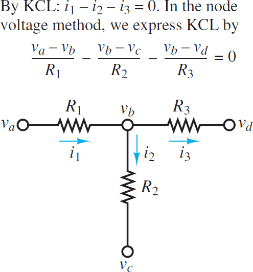
Let's trace the logic for the equation at node vb in the image, assuming currents leaving are positive:
- KCL with currents: (assuming all are leaving)
- Express each current with Ohm's Law:
- Substitute into the KCL equation:
Now we have an equation that contains only voltages and resistances. If we write one such equation for every unknown node voltage in a circuit, we create a system of linear equations. Since you are studying linear algebra, you can appreciate that this system can be solved to find all the node voltages. We will dedicate a full lesson to this powerful technique in Module 2. For now, the key is to see how KCL serves as its backbone.
Conclusion
In this lesson, you've added a fundamental law to your circuit analysis toolkit.
Key Takeaways:
- Kirchhoff's Current Law (KCL) is a direct result of the conservation of charge.
- It states that the total current entering a node must equal the total current leaving it ().
- Alternatively, using a sign convention (e.g., entering is positive), the algebraic sum of all currents at a node is zero ().
- KCL, when combined with Ohm's Law, forms the basis of Nodal Analysis, a powerful and systematic method for solving complex circuits.
We have now seen how current behaves at a junction. In the next lesson, we will explore the companion law, Kirchhoff's Voltage Law (KVL), which describes the behavior of voltages around a closed loop in a circuit. These two laws, KCL and KVL, are the absolute cornerstones of all DC circuit analysis.