Hello! Welcome to your second lesson.
In our first session, we established the crucial first step in any structural analysis problem: calculating the external support reactions using the equations of static equilibrium. You learned how to handle point loads, uniformly distributed loads (UDL), and uniformly varying loads (UVL) for this purpose.
Now, we move from the external forces to the internal forces. Your ultimate goal is to use Castigliano's theorem, which is based on strain energy. The formula for bending strain energy requires an expression for the internal bending moment along the beam. Today's lesson is entirely focused on mastering how to find that expression, which we call M(x).
1. The Method of Sections: Revealing Internal Forces
To find the internal bending moment, we use a technique called the method of sections. The idea is simple: if the entire beam is in equilibrium, then any piece of it must also be in equilibrium.
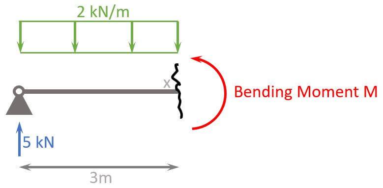
We make an imaginary "cut" at an arbitrary location x along the beam. This cut splits the beam into two parts and "reveals" the internal forces at that location: a shear force V(x) and a bending moment M(x). By drawing a free-body diagram (FBD) of the segment on one side of the cut, we can use the equilibrium equations to solve for M(x).
A new expression for M(x) is required for each segment of the beam. A segment is a portion of the beam between any two points where the loading condition changes (e.g., between a support and a point load, or where a UDL starts or ends).
The following video provides an excellent overview of this concept and lays out the general procedure.
SA07U: Shear & Moment Equations
To start, let's watch this video from Dr. Structure that outlines the general strategy for finding moment equations. It explains why we need different equations for different parts of the beam and lays out a clear, four-step process.
Watch from the beginning to 04:55. Focus on two key ideas: Why concentrated loads or changes in distributed loads create different 'segments' requiring separate equations (00:06 - 01:54). The four-step process he outlines for formulating these equations (01:54 - 04:55).
As the video explained, our process will be:
- Calculate support reactions (which you learned in the previous lesson).
- Identify the beam segments based on changes in loading.
- Make a cut at an arbitrary distance
xwithin a segment and draw the Free Body Diagram (FBD) of the portion to the left of the cut. - Write the equilibrium equation for the sum of moments about the cut (
ΣM_cut = 0) and solve forM(x).
Sign Convention: We will use a standard sign convention. When we cut a beam and look at the left-hand segment, a positive internal bending moment M acts in a counter-clockwise direction.
2. Case 1: Beams with Point Loads
When a beam is subjected only to point loads, the bending moment M(x) will be a linear function of x (e.g., M(x) = ax + b). You will need a different linear function for each segment between the loads.
Let's see this in action.
SA07U: Shear & Moment Equations
Now let's see the four-step method applied to a simply supported beam with a single point load. This example will clearly show you how to create two separate moment expressions, M(x), one for each segment of the beam.
Watch from 04:55 to 08:04. After finding the reactions (Step 1), notice how he performs Steps 2-4 for two separate segments: Segment 1 (0 ≤ x < 4): He cuts before the load, and the moment equation is M = 6x. Segment 2 (4 < x ≤ 10): He cuts after the 10 kN load, and the equation changes to include it, resulting in M = 40 - 4x.
This example perfectly illustrates the process. For each segment, we define our variable x from the left end of the beam, draw the FBD for that cut, and solve for M(x).
3. Case 2: Uniformly Distributed Loads (UDL)
When a segment includes a UDL of intensity w (e.g., in kN/m), the process is the same, but we must account for the distributed load acting on the cut portion.
For a cut at a distance x into a UDL:
- The total force from the UDL on the FBD is
w × x. - This force acts at the centroid of the rectangular load, which is a distance of
x/2from the cut.
This will result in a quadratic function for the bending moment (M(x) = ax² + bx + c).
SA07U: Shear & Moment Equations
Next, let's look at a Uniformly Distributed Load (UDL). The key here is to correctly represent the portion of the UDL acting on the free-body diagram of our cut section.
Watch from 08:04 to the end (11:07). For the first cut within the UDL (0 ≤ x < 5), notice the moment from the UDL is 100x * (x/2) = 50x². For the second cut past the UDL (x > 5), the entire UDL is treated as a single concentrated load of 100*5 = 500 N, and its moment arm about the cut is (x - 2.5).
4. Case 3: Uniformly Varying Loads (UVL)
The triangular load is the most complex case, but it follows the same principles. The key is to determine the height (intensity) of the load, w(x), at the location of the cut x. We do this using similar triangles.
For a triangular load that starts at 0 and increases to an intensity of w_max over a length L:
- The load intensity at position
xisw(x) = (w_max / L) * x. - The total force from the UVL on the FBD (the area of the small triangle) is
(1/2) * base * height = (1/2) * x * w(x). - This force acts at the centroid of the small triangle, which is a distance of
x/3from the cut.
This process results in a cubic function for the bending moment (M(x) = ax³ + bx² + cx + d).
Statics: Lesson 61 - Shear Moment Diagram, The Equation Method
The final case we need to cover is the Uniformly Varying Load (UVL). The key is to find the height of the load at your cut position 'x' using similar triangles.
Watch from 10:07 to 13:59. This section is dense but covers everything you need: Finding the load height at x (10:07 - 10:50): The instructor finds the slope of the load, m = 9/12 = 3/4, so the height at x is w(x) = (3/4)x. Deriving V(x) and M(x) (10:50 - 13:59): Observe how the force from the triangular load on the FBD is (1/2) * x * (3/4)x = (3/8)x² and its moment arm about the cut is x/3. This leads directly to the final cubic expression for M(x).
Conclusion
You have now learned the systematic method for deriving the internal bending moment expression, M(x), for any segment of a beam under the three common load types. This is the most calculation-intensive part of the foundation, and mastering it is essential for what comes next.
Key Takeaways:
- The Method of Sections is used to find internal forces by cutting the beam and analyzing the equilibrium of a segment.
- A new
M(x)expression is needed for each beam segment where the loading changes. - The complexity of the
M(x)function depends on the load type:- Point Load →
M(x)is Linear (ax + b) - UDL →
M(x)is Quadratic (ax² + bx + c) - UVL →
M(x)is Cubic (ax³ + ...)
- Point Load →
In our next lesson, we will use these M(x) expressions to define the bending strain energy in a beam using the formula U = ∫ M²/(2EI) dx. You will see then why being able to correctly write M(x) is so critical.