Hello! Welcome back to our course on General Relativity.
In our last few lessons, we've focused on the weak-field limit of GR, culminating in a detailed analysis of gravitational wave generation. We derived the quadrupole formula, applied it to binary systems, and found that the orbital decay of the Hulse-Taylor pulsar provides stunning indirect confirmation of our theory. We also characterized the "chirp" signal—the rising frequency and amplitude of gravitational waves from an inspiraling binary—which is the primary target for direct detection.
Today, we will address the crucial next question: how do we actually detect these incredibly faint ripples in spacetime? This lesson will cover the learning outcome: Describe the basic principles of gravitational wave detection by laser interferometers (LIGO/Virgo). We will bridge the gap between the theoretical strain tensor, , and the experimental reality of measuring its effects.
1. The Physical Effect of a Gravitational Wave
First, let's solidify what we are trying to measure. A gravitational wave is a transverse wave of spacetime curvature. As it passes, it alters the physical, or proper, distance between free-falling objects.
You may have heard the question: "If the wave stretches space, doesn't it also stretch the ruler you're using to measure it, making the effect undetectable?" This is a subtle but important point. The key is that the components of a physical ruler are held together by electromagnetic forces, not gravity. The ruler's length is determined by the equilibrium of these internal forces, and it resists the stretching of space. A detector exploits this by measuring the change in distance between "free-falling" mirrors relative to the size of the apparatus itself.
Let's explore this distinction between coordinate distance and physical distance more formally.
Brief introduction to gravitational waves: theory, production ...
This resource provides a clear discussion on the difference between coordinate displacement and physical displacement in the context of a passing gravitational wave. This is a fundamental concept for understanding detection.
Please read Section 3.1 'Gauge and reference frames' and Section 3.2 'Coordinate displacements versus physical displacements' (pages 15-17). Focus on how, in the TT gauge, the coordinate distance between test particles remains constant, but their physical (proper) distance oscillates. This oscillation of proper distance is the observable effect.
As the text explains, the physical distance between two points separated by a coordinate distance in the presence of a wave perturbation is:
The relative change in physical length, which we call the strain, is . It is this dimensionless quantity, , that gravitational wave detectors are designed to measure. For typical astrophysical events detected by LIGO, is on the order of , an unimaginably small number.
2. The Michelson Interferometer: A Strain Meter
To measure such a minuscule strain, we need an exceptionally sensitive instrument. The solution is laser interferometry. The basic design used is a Michelson interferometer.
Let's watch a video that explains the core principle of how an interferometer detects the stretching and squeezing of space.
Exploring the Gravitational Wave Universe
This video provides an excellent visualization of how a gravitational wave affects a ring of test particles and how a Michelson interferometer is perfectly suited to measure this effect.
Watch the segment from 00:12:59 to 00:14:19. Pay close attention to the animation of the ring of particles being deformed by the wave, and how this directly translates to the differential arm length change in the interferometer.
As the video shows, a gravitational wave propagating perpendicular to the plane of the detector will, for a '+' polarization aligned with the arms:
- Stretch the space along one arm ().
- Simultaneously compress the space along the other arm ().
The interferometer is designed to be exquisitely sensitive to this difference in arm length, .
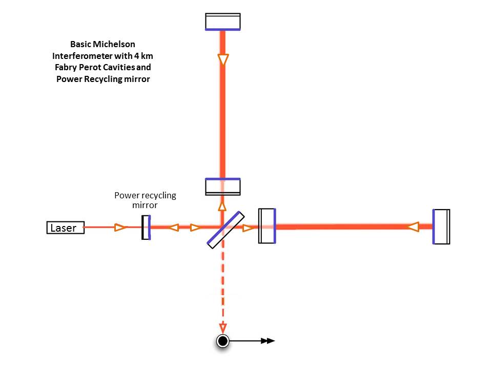
The laser light that travels down each arm returns to the beam splitter and interferes. The instrument is set up so that, in the absence of a gravitational wave, the light from the two arms interferes destructively, and no light reaches the photodetector. When a gravitational wave passes, it changes the relative path lengths, disrupting this perfect cancellation. A tiny amount of light "leaks" through to the photodetector, creating a signal that is proportional to the gravitational wave strain .
3. Detector Response and Antenna Patterns
A detector's sensitivity is not the same for all directions or polarizations. The response depends on the geometry of the detector relative to the incoming wave. This relationship is captured by the antenna pattern functions.
For a rigorous understanding, we can define a detector tensor, , that encapsulates the geometry of the interferometer. If and are unit vectors along the two arms, the detector tensor is:
The measured strain signal is then simply the contraction of the gravitational wave tensor with the detector tensor:
Since the wave can be decomposed into its polarization components, , the signal becomes:
The terms and are the antenna pattern functions. They are scalar numbers that depend on the source's location in the sky () and the wave's polarization orientation ().
Let's delve into the formal derivation of this relationship.
The Geometry of Gravitational Wave Detection - LIGO DCC
This document provides a concise and rigorous derivation of the detector tensor and antenna pattern functions. It's the perfect mathematical bridge from the theoretical wave tensor to the measured signal.
Please read Section 2.1 'The Detector Tensor' and Section 2.2 'Antenna response functions' (pages 5-7). Follow the logic from the derivation of the roundtrip travel time of a photon to the definition of the measured strain h as a contraction h = h↔ : d↔. Then see how this leads to the familiar expression h = h+F+ + h×F×.
The key implication is that a single detector is "blind" to certain directions and polarizations (where and are both zero). This is a primary motivation for having a global network of detectors (like LIGO in the US, Virgo in Italy, and KAGRA in Japan). By combining signals from multiple detectors with different orientations, we can reconstruct the full signal and pinpoint the source's location on the sky.
4. The "Advanced" in Advanced LIGO/Virgo
Measuring a strain of is a monumental challenge. For LIGO's 4 km arms, this corresponds to measuring a change in length of meters—about 1/1000th the diameter of a proton. A basic Michelson interferometer cannot achieve this. Several key innovations are required.
This next video provides an overview of the technologies that give Advanced LIGO its incredible sensitivity.
Exploring the Gravitational Wave Universe
This video explains the crucial upgrades that make detectors like LIGO sensitive enough to see gravitational waves, from the immense scale to the sophisticated optical and isolation systems.
Please watch the segment from 00:15:46 to 00:24:04. It covers three key concepts: Long Arms: Why the detectors are so large. Quiet Mirrors: The ingenious multi-stage seismic isolation and suspension systems that keep the mirrors almost perfectly still. Precise Measurement: The use of Fabry-Pérot cavities and power recycling to boost the effective laser power and arm length.
Let's summarize the key enhancements:
- Long Arms: The physical displacement is . By making as large as possible (4 km for LIGO), we maximize the absolute displacement that we need to measure.
- Fabry-Pérot Cavities: A semi-transparent mirror is placed near the beam splitter in each arm. This forms an optical resonant cavity. The laser light bounces back and forth about 300 times before exiting, effectively increasing the optical path length from 4 km to over 1200 km. This multiplies the phase shift caused by the gravitational wave by the same factor.
- Power Recycling: A mirror is placed between the laser and the beam splitter to recycle light that is reflected from the arms back towards the laser. This boosts the laser power circulating in the interferometer from ~60 watts to hundreds of kilowatts, which reduces the quantum uncertainty in the measurement (shot noise).
- Seismic Isolation: The mirrors (test masses) must be shielded from all non-gravitational noise. Ground vibrations, even from distant earthquakes or waves crashing on a coast, are millions of times larger than the expected signal. The mirrors are suspended by a multi-stage pendulum system combined with active feedback controls, making them arguably the most isolated objects on Earth.
5. Signal from the Noise
Even with these technologies, the raw data from a detector is overwhelmingly dominated by noise. The final step is to extract the faint astrophysical signal from this noisy background. The key technique is matched filtering.
In the previous lesson, we derived the precise shape of the "chirp" signal from an inspiraling binary. Because we know what we are looking for, we can create theoretical templates of this waveform. The matched filtering algorithm continuously compares these templates with the incoming data stream, looking for a statistically significant match.
Talk 1 - Surfing the Gravitational Waves - By Prof. Sanjit Mitra ( IUCAA, Pune )
This final video segment explains the concept of matched filtering—the technique used to find a known signal (our chirp template) buried in a noisy data stream.
Watch the segment from 00:39:14 to 00:42:44. The speaker provides a good conceptual explanation of how you can find a 'needle in a haystack' if you know exactly what the needle looks like.
When the template and a segment of data align, the algorithm produces a high signal-to-noise ratio (SNR), signaling a potential detection. This reliance on accurate theoretical models demonstrates the deep synergy between theory and experiment in gravitational wave astronomy.
Test your understanding!
A gravitational wave from a binary neutron star merger is propagating perpendicular to the plane of a LIGO-like detector (). Its '+' polarization is perfectly aligned with the detector's arms. A wave from a different source, a binary black hole merger, arrives from a 'blind spot' on the sky for this detector. What is the value of the antenna pattern functions, and , in each case? What does this imply about the measured strain for the second event?
Show answer
For the binary neutron star event, the wave is coming from directly overhead, which is a direction of maximum sensitivity. With the '+' polarization aligned with the arms, the antenna pattern function will be at its maximum value (), and by orthogonality, will be zero. The detector will measure .
For the binary black hole event, arriving from a 'blind spot' means that both antenna pattern functions are zero: and . This implies that regardless of the intrinsic strength of the gravitational waves ( and ), the measured strain at this detector will be zero: . This highlights why a network of detectors is essential for observing the entire sky.
Conclusion
In this lesson, we have explored the fundamental principles of gravitational wave detection, from the physical effect of a wave on proper distance to the advanced technologies that enable its measurement.
Key Takeaways:
- Gravitational wave detectors measure the strain, , which is the change in physical distance between free-falling objects.
- Laser interferometers are used to measure this strain by detecting the differential change in arm lengths, which manifests as a change in the interference pattern of laser light.
- The detector's response to an incoming wave is described by antenna pattern functions, and , which depend on the source's sky position and polarization.
- Achieving the necessary sensitivity () requires advanced techniques: long arms, Fabry-Pérot cavities, power recycling, and extreme seismic isolation.
- Matched filtering is used to find the theoretically-predicted "chirp" signals within the noisy detector data.
Preview of Next Lesson:
Having concluded our multi-lesson foray into the weak-field limit and gravitational waves, we will now pivot to the strong-field regime. This is where General Relativity reveals its most exotic and fascinating predictions. In the next lesson, we will begin Module 4 by tackling its first learning outcome: Derive the Schwarzschild metric as the unique static, spherically symmetric vacuum solution (Birkhoff's theorem). This will be our first exact solution to the full Einstein Field Equations and will serve as the foundation for understanding non-rotating black holes.