Recommended resources
The freely available resources this lesson will direct you to.
Hello! Welcome back to our course on electricity.
In the last lesson, we established the language of AC circuits, learning how to describe alternating voltage and current as sinusoidal waves and how to quantify them using peak and RMS values. We now have a defined AC source, . The natural next question is: what happens when we connect this source to the fundamental circuit components—resistors, inductors, and capacitors?
Today, we'll explore exactly that. Our learning outcome is to describe the fundamental behavior of resistors, capacitors, and inductors in AC circuits. You'll discover that while a resistor's behavior is quite familiar, inductors and capacitors introduce a crucial new concept: they not only oppose the current but also shift its timing, or phase, relative to the voltage. This is the key that unlocks the analysis of all AC circuits.
A Quick Recap: Resistance, Reactance, and Impedance
Before diving into the components, let's define our terms. In DC circuits, the opposition to current is simply resistance (R). In AC circuits, the situation is more complex.
AC circuits, alternating current electricity
This article from the University of New South Wales gives a concise introduction to the key terminology we'll be using.
Please read the section titled 'What are impedance and reactance?'. Focus on the definitions of impedance (Z), resistance (R), and reactance (X) as different types of opposition to current in AC circuits.
As you just read:
- Resistance (R) is the opposition to current that does not create a phase shift between voltage and current.
- Reactance (X) is the opposition to current that creates a 90° phase shift between voltage and current. We'll see this is the property of ideal inductors and capacitors.
- Impedance (Z) is the general term for the total opposition to current in an AC circuit. It's a combination of resistance and reactance.
Now, let's examine how each component contributes to this.
1. Resistors in AC Circuits
The resistor is the most straightforward component. Its behavior in an AC circuit is very similar to its behavior in a DC circuit.
EEVblog 1660 - AC Basics Tutorial Part 4: Resistors, Capacitors, Inductors
Let's watch a segment from an EEVblog tutorial that explains the resistor's behavior in an AC circuit.
Watch from 00:30 to 04:00. Note how Ohm's Law still applies for instantaneous and RMS values, and critically, that the voltage and current waveforms are perfectly aligned, or 'in phase'.
As the video explained, for a resistor:
- Ohm's Law applies directly: The voltage across the resistor is proportional to the current through it at every instant in time. We can write this for instantaneous values () or for RMS values ().
- Voltage and current are in phase: The peaks and troughs of the voltage and current waveforms occur at the same time. The phase difference is 0°.
- Frequency has no effect: The resistance is a constant value and does not depend on the frequency of the AC source.
The water analogy for resistance is a simple constriction in a pipe—it impedes flow regardless of whether the flow is steady (DC) or oscillating (AC).
2. Inductors in AC Circuits
Inductors, which are typically coils of wire, behave very differently. Their defining property is that they resist changes in current. Since AC current is, by definition, constantly changing, an inductor will continuously oppose it.
The Intuition: Electrical Inertia
A fantastic analogy for an inductor is a heavy water wheel or turbine in a pipe.
What are Resistance Reactance Impedance
This video provides an excellent water-flow analogy to build an intuition for how inductors work.
Watch from 06:46 to 08:30. Focus on the water wheel analogy. Notice how the applied force (voltage) must build up before the water flow (current) can get going, and how the wheel's inertia tries to keep the water flowing even when the force is removed. This creates a delay, or lag.
This "electrical inertia" means that when you apply a voltage across an inductor, the current takes time to build up. This leads to the most important characteristic of an inductor in an AC circuit.
Voltage Leads Current
In a purely inductive circuit, the current lags the voltage by 90° ( radians). This means the current reaches its peak value a quarter of a cycle after the voltage reaches its peak.
A common mnemonic to remember the phase relationships for inductors (L) and capacitors (C) is "CIVIL":
- In a Capacitor, I (current) leads V (voltage).
- In an Inductor, V (voltage) leads I (current).
Inductive Reactance ()
The opposition an inductor presents to alternating current is called inductive reactance, denoted . Unlike resistance, it is dependent on frequency.
EEVblog 1660 - AC Basics Tutorial Part 4: Resistors, Capacitors, Inductors
The EEVblog video provides a clear explanation of inductive reactance and its formula.
Now watch from 05:09 to 12:20. Pay close attention to the introduction of 'inductive reactance' (X_L), its formula, and how it relates to frequency. The video also introduces the complex number notation j\omega L, which is a preview of what we'll use in the next lesson to handle the 90° phase shift.
The key formula for inductive reactance is:
Where:
- is the inductive reactance in Ohms ().
- is the angular frequency in rad/s.
- is the frequency in Hz.
- is the inductance in Henrys (H).
This formula shows that inductive reactance is directly proportional to frequency. If you double the frequency, the current changes twice as fast, and the inductor opposes it twice as strongly. At DC (), an ideal inductor has zero reactance and acts like a short circuit (just a piece of wire).
Your background in calculus provides a more formal explanation for the 90° lead. The voltage across an inductor is given by Faraday's Law: . If the current is a sine wave, , its derivative (the rate of change) is a cosine wave: . Since , the voltage is a sine wave that is shifted 90° ahead of the current.
3. Capacitors in AC Circuits
Capacitors store energy in an electric field. Their defining property is that they oppose changes in voltage.
The Intuition: The Elastic Barrier
A great analogy for a capacitor is an elastic membrane dividing a water pipe.
What are Resistance Reactance Impedance
Let's return to the analogy video to understand capacitors.
Watch from 09:12 to 11:00. Focus on the elastic chamber analogy. Water (current) flows as the membrane stretches under pressure (voltage). Critically, the flow is maximum when the membrane is just starting to stretch (voltage is zero), and the flow stops when the membrane is fully stretched (voltage is maximum).
This behavior, where current must flow before a voltage can build up across the capacitor, leads to its defining AC characteristic.
Current Leads Voltage
In a purely capacitive circuit, the current leads the voltage by 90° ( radians). The current reaches its peak a quarter of a cycle before the voltage across the capacitor does. This is the "C-I-V" part of the "CIVIL" mnemonic.
Capacitive Reactance ()
The opposition a capacitor presents to alternating current is called capacitive reactance, denoted .
EEVblog 1660 - AC Basics Tutorial Part 4: Resistors, Capacitors, Inductors
Let's complete the EEVblog tutorial by looking at capacitors.
Watch from 13:19 to 16:25. Note the formula for 'capacitive reactance' (X_C) and its inverse relationship with frequency. Again, note the introduction of complex notation, which we will use later.
The key formula for capacitive reactance is:
Where:
- is the capacitive reactance in Ohms ().
- is the capacitance in Farads (F).
This formula shows that capacitive reactance is inversely proportional to frequency. If you double the frequency, the capacitor has only half the time to charge up for each cycle. This means less voltage builds up for the same amount of current flow, resulting in half the opposition. At DC (), an ideal capacitor has infinite reactance and acts like an open circuit, blocking current completely once charged.
Again, for a formal explanation, the relationship is . If the voltage is a sine wave, , the current is its derivative, a cosine wave: . The current is therefore 90° ahead of the voltage.
Summary of Component Behaviors
We have now seen how resistors, inductors, and capacitors each behave in an AC circuit. They each oppose current, but in very different ways.
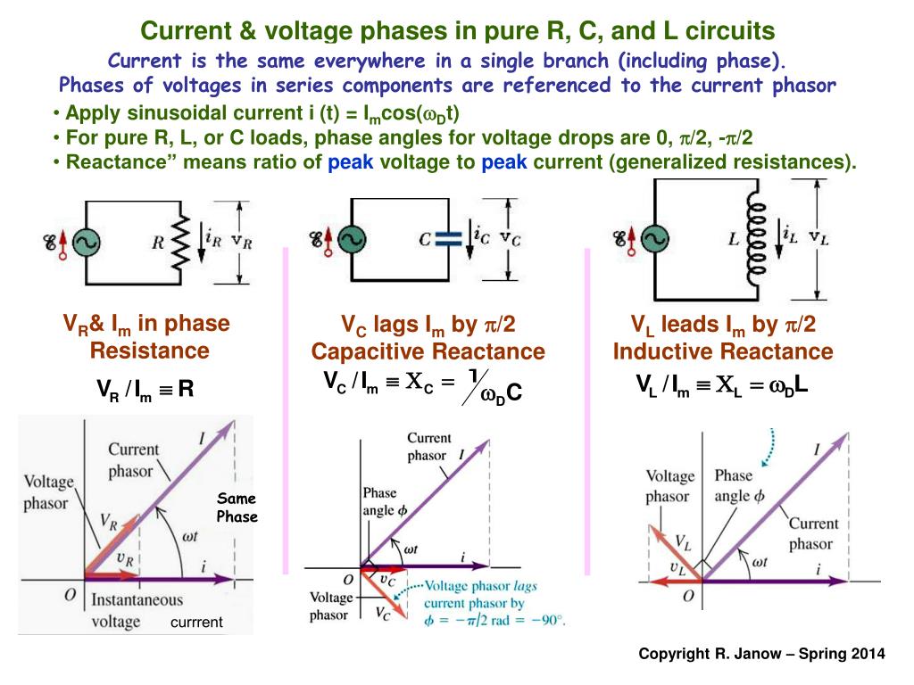
For a more detailed summary, including the mathematical underpinnings, the UNSW Physics page is an excellent resource to review.
AC circuits, alternating current electricity
This resource provides excellent animated diagrams and a final summary table that consolidates everything we've discussed.
Skim through the sections on 'Resistors', 'Capacitors', and 'Inductors' to see the animated representations of the phase shifts. Then, carefully study the summary table and graph in the 'Impedance of components' section. This brings all the concepts together.
Test your understanding!
Consider two separate circuits:
- A 10 mH inductor is connected to a variable-frequency AC source.
- A 100 µF capacitor is connected to another variable-frequency AC source.
- What happens to the inductive reactance () if the frequency is doubled?
- What happens to the capacitive reactance () if the frequency is doubled?
- At what frequency would they have the same reactance?
Show answer
- Inductive reactance is . It is directly proportional to frequency. If the frequency doubles, the inductive reactance also doubles.
- Capacitive reactance is . It is inversely proportional to frequency. If the frequency doubles, the capacitive reactance is halved.
- To find the frequency where they have the same reactance, we set : Solving for : Plugging in the values ( H, F):
This special frequency where the reactances are equal is known as the resonant frequency, a very important concept in circuit design that we will encounter again.
Conclusion
In this lesson, we dissected the fundamental AC behavior of the three passive circuit elements.
Key Takeaways:
- Resistors: Oppose current with resistance (). Voltage and current are in phase. Resistance is independent of frequency.
- Inductors: Oppose current with inductive reactance (). Voltage leads current by 90°. Reactance increases with frequency.
- Capacitors: Oppose current with capacitive reactance (). Current leads voltage by 90°. Reactance decreases with frequency.
Preview of the Next Lesson:
We've seen that inductors and capacitors introduce phase shifts. But what happens when we combine these components in a single circuit? Simply adding their ohms values doesn't work because of these phase differences. In the next lesson, we will analyze the phase relationship between voltage and current in resistive, inductive, and capacitive loads more formally. We will learn how to use phasor diagrams as a graphical tool to represent and add these phase-shifted voltages and currents, setting the stage for calculating the total impedance of a complete AC circuit.