Recommended resources
The freely available resources this lesson will direct you to.
- Power factor explained | Active Reactive Apparent Power correctionwww.youtube.com
- AC Power Analysis: Complex power, Active power, Reactive power, Apparent power, and Power factorwww.youtube.com
- What is Active, Reactive, Apparent and Complex Power?www.electricaltechnology.org
- Chapter 12 Alternating-Current Circuitsweb.mit.edu
Hello! Welcome to your fifth lesson.
In our last session, we mastered the use of complex numbers to calculate the impedance of series RLC circuits. We saw how total impedance, , elegantly combines resistance and reactance, and how its magnitude and phase angle determine the relationship between voltage and current.
Today, we will build directly on that foundation to address the learning outcome: Calculate real, reactive, and apparent power in AC circuits. In DC circuits, power is simple: . In AC circuits, the phase shift between voltage and current introduces a fascinating complexity. We'll dissect this into three distinct types of power, which is crucial for understanding everything from appliance energy ratings to the design of power grids.
The Nuances of AC Power
In an AC circuit, the instantaneous power is still the product of instantaneous voltage and current, . However, because and are sinusoids that can be out of phase, this product can become negative during parts of the cycle.
- Positive Power: Energy is being delivered from the source and consumed by the load (e.g., dissipated as heat in a resistor).
- Negative Power: Energy is being returned to the source from the load.
This "sloshing" of energy is unique to AC circuits with reactive components (inductors and capacitors).
Power factor explained | Active Reactive Apparent Power correction
To build your intuition, let's watch a video that visualizes this phenomenon. It clearly shows how introducing an inductor creates 'negative power regions'.
Please watch from 02:44 to 11:40. Focus on how the phase lag caused by the inductor leads to negative power, and how this gives rise to three distinct concepts of power.
As the video explained, this energy flow can be broken down into three key quantities:
- Real Power (P): The average power over a full cycle that results in a net transfer of energy, performing useful work (e.g., generating heat, light, or mechanical motion). Its unit is the Watt (W).
- Reactive Power (Q): This represents the energy that is temporarily stored in electric or magnetic fields and then returned to the source. It does no useful work but is essential for the operation of inductive and capacitive loads. Its unit is the Volt-Ampere Reactive (VAR).
- Apparent Power (S): This is the "total" power that the circuit appears to be drawing, calculated simply by multiplying the RMS voltage and RMS current, . It's the total capacity the source and wiring must be able to handle. Its unit is the Volt-Ampere (VA).
Complex Power and The Power Triangle
Given your background, the most direct and powerful way to handle these three quantities is by defining Complex Power, denoted by the bold letter . It's a complex number whose real part is the real power and whose imaginary part is the reactive power .
Complex power can be calculated directly from the voltage and current phasors:
where is the complex RMS voltage phasor, and is the complex conjugate of the RMS current phasor.
Why the conjugate? Let the voltage and current phasors be and . The phase angle of the impedance is . By using the conjugate of the current (), the calculation becomes:
Using Euler's formula, we can expand this into its rectangular form:
By comparing this to , we arrive at the standard formulas:
- Real Power:
- Reactive Power:
- Apparent Power:
The quantity is called the power factor (PF). It's the ratio of real power to apparent power, , and tells us how effectively the supplied power is being used to do work.
This relationship between P, Q, and S forms a right-angled triangle in the complex plane, known as the power triangle.
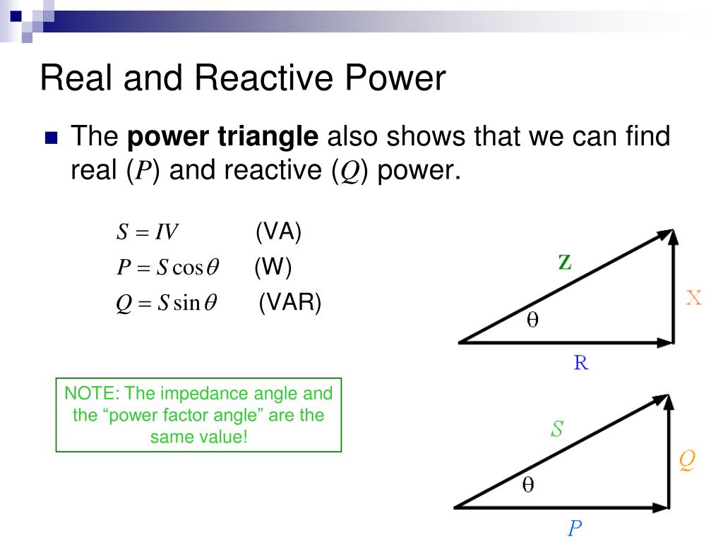
This image reveals a profound connection: the power triangle is simply the impedance triangle scaled by the square of the RMS current, since:
A Deeper Dive into Complex Power
The following video provides an excellent summary of these concepts, focusing on the definition of complex power and its relationship to the power factor.
AC Power Analysis: Complex power, Active power, Reactive power, Apparent power, and Power factor
This video clearly defines complex power as a quantity containing active (real) and reactive power as its real and imaginary parts, and introduces apparent power as its magnitude.
Please watch from 14:02 to 17:13. This segment neatly ties together the concepts of complex power, the power triangle, and the power factor.
Calculation Walkthrough
Let's put this into practice. Suppose we have a series RLC circuit with connected to a , source. Let's find P, Q, S, and the power factor.
-
Find the impedance in polar form:
- So, .
-
Find the RMS current: We use Ohm's Law for AC, .
- Let's set the voltage phase as our reference, .
- .
-
Calculate Complex Power, S:
- .
- .
-
Find P, Q, S, and PF:
- Apparent Power (S): The magnitude of is . (Also, ).
- Real Power (P): .
- Reactive Power (Q): .
- Power Factor (PF): . Because the phase angle is positive (implying an inductive impedance), the current lags the voltage, so we say the power factor is 0.6 lagging.
Test your understanding!
An electric motor is connected to a RMS supply and draws an RMS current of . A wattmeter connected to the circuit measures a real power consumption of .
Calculate:
- The apparent power (S).
- The power factor (PF).
- The reactive power (Q) consumed by the motor.
Show answer
- Apparent Power (S):
- Power Factor (PF): The power factor is the ratio of real power to apparent power.
Since motors are inductive loads, we can specify this as 0.75 lagging. - Reactive Power (Q): We use the power triangle relationship, .
Formula Summary
For a quick reference, the following resource compiles the definitions and formulas for all three types of power, and also introduces the concept of complex power.
What is Active, Reactive, Apparent and Complex Power?
This article from Electrical Technology serves as an excellent reference, clearly defining active, reactive, apparent, and complex power and listing their respective formulas.
Scan through the sections defining 'Active Power (P)', 'Reactive Power (Q)', 'Apparent Power (S)', and 'Complex Power'. This will help consolidate the formulas we've discussed. Pay special attention to the units (W, VAR, VA) for each.
Conclusion
Today, we've unraveled the different facets of power in AC circuits, moving beyond the simple DC case to a more nuanced model that is essential for real-world applications.
Key Takeaways:
- Real Power (P) is the "useful" power that does work, measured in Watts (W).
- Reactive Power (Q) is the power exchanged with reactive components, measured in Volt-Amps Reactive (VAR). Inductors consume reactive power (), while capacitors supply it ().
- Apparent Power (S) is the vector sum of real and reactive power, representing the total power the source must deliver. It is measured in Volt-Amps (VA).
- Complex Power () elegantly combines these quantities and can be calculated as .
- The Power Triangle graphically represents the relationship .
- The Power Factor () measures the efficiency of power usage.
Preview of the Next Lesson:
We've defined the power factor, but why is it so important? A low power factor means that for a given amount of useful work, a larger total current is flowing through the wires. In our next lesson, we will explore this further to explain the concept of power factor and its impact on power generation and transmission efficiency. We'll see why industrial consumers are often penalized for having a low power factor and how it can be corrected.