Recommended resources
The freely available resources this lesson will direct you to.
Hello. Last lesson separated a shutter’s local exposure time from the time it takes to uncover the whole frame. There is another condition hidden in those timing models: the recording surface must be in the intended place while light reaches it. A perfectly timed shutter cannot produce a sharp, correctly spaced series of photographs if the film bows away from focus or advances an uncertain distance.
This lesson follows that mechanical problem from rigid plates to flexible roll film. You will see how a holder or gate establishes the image-plane reference, how a pressure plate controls film shape, and how transport and counting mechanisms make successive exposures repeatable. Allow about 40 minutes, including the short demonstrations and manual passages.
Registration has two meanings
A camera must control both depth and position within the frame. Depth registration means placing the photosensitive surface at the distance for which the lens was focused. In-plane registration means placing its image area under the gate, with predictable boundaries and—when needed—keeping it there for another exposure.
These errors have different signatures. Film displaced along the optical axis produces defocus; film shifted sideways can move a composition or spoil the alignment of two exposures. Film advanced too little can overlap adjacent frames, while film advanced too far wastes material. A frame counter can report that an advance occurred, but the counter itself cannot prove that the film reached the right position.
Flatness matters quantitatively. For a distant subject and a paraxial image cone, an axial film displacement produces a defocus-circle diameter of approximately
where is the f-number. This is the same geometric principle used earlier to set a circle-of-confusion criterion. As an illustration, a local displacement of at gives . That could be conspicuous in an enlarged image even if every part of the shutter worked correctly. At close focus, the appropriate image-side cone angle replaces this simple distant-subject approximation.
The critical surface is the emulsion, not merely the back of the film base. Film thickness, backing material, and how the strip lies in its channel all affect where that emulsion ends up.
Rigid plates and sheet-film holders
A glass plate offered an immediate mechanical advantage: it was relatively rigid and could be seated against defined supports in a light-tight holder. When focusing on a view camera’s ground glass, however, the photographer views an image on one surface and later substitutes a photosensitive plate or sheet. The camera and holder must be made so that the emulsion occupies the same intended focal plane as the ground-glass image. The relevant offsets include glass thickness, the holder’s seating surfaces, and the position of the emulsion in the holder.
A holder therefore does more than protect film from light. Its edges and retaining features locate the sheet; its mounting surfaces locate the holder relative to the camera; and its dark slide lets the holder be attached or removed without exposing its contents. A double-sided holder can present a second sheet by being turned over. None of these features can compensate for a sheet that has been inserted incorrectly or does not lie as intended.
The Grafmatic demonstration by Craig Sheaks shows a more elaborate holder that stores and cycles several individual sheets. Watch it as an example of how sheet-film positioning, light shielding, and exposure indication can be combined in one mechanism—not as the operating procedure for every sheet-film holder.
4x5 Grafmatic Film Back Operation | Large Format Film Photography
In “4x5 Grafmatic Film Back Operation,” Craig Sheaks demonstrates how individual sheets are retained and brought into position within a multi-sheet back.
Watch loading the sheets to see the septums, retaining tracks, and film orientation. Then watch position and shielding and cycling a sheet. Track three distinct jobs: locating the sheet for exposure, shielding the other sheets, and updating the visible indication. The demonstrated instruction to reinsert the slide before exposure is specific to this multi-sheet back; a conventional single-sheet holder is operated differently.
The holder solves positioning one sheet at a time. Flexible roll film changes the engineering problem: the recording material must move freely between exposures yet come to rest repeatedly in a controlled plane.
The gate and pressure plate: a controlled channel
The film gate is the camera opening that defines the exposed image area. Around it, precisely located surfaces support or guide the film near its edges. A pressure plate, usually mounted on the camera back, supports the film from behind and biases it toward the intended path. The film travels through the clearance between these parts; the plate does not simply clamp the entire image area immovably against the aperture.

The Film gate cross-section makes an important distinction visible: the plate supplies controlled restraint, while the rail geometry helps define where the film runs. If the channel is too loose, curl or local bowing can move the emulsion away from the focal plane. If it is too tight, transport force rises and film or backing may be scratched or damaged. Spring loading accommodates modest thickness variation without making the camera back’s position alone the precision reference.
An original pressure-plate patent makes the thickness problem unusually explicit. Its design changes the channel clearance to accommodate film with or without backing paper. Read the purpose and the description of its spring-supported plate and stepped guides; the point is the tolerance problem, not the particular selector-knob design.
Read this camera pressure-plate patent to see how an apparently small change in material stack-up becomes a mechanical design requirement.
In the opening description, begin with the stated problem; focus on why backing paper calls for a different clearance. In the subsequent description accompanying Figures 1–4, find the paragraph beginning “a camera body I having a film exposure frame or opening 2 therein.” Read the component layout, then the later paragraph beginning “the external guide rails 4” through the stepped clearances. Follow which parts provide spring force and which set the spacing; some characters in the patent transcription are imperfect.
This is an example of tolerance allocation. The spring is useful because it supplies force over a range of positions. The hard surfaces and steps are useful because they make that range repeatable. Neither alone guarantees perfectly flat film: roll memory, variations in film thickness, trapped debris, and damage to the plate or rails can still produce local errors. The diagram’s millimetre dimensions should likewise be treated as dimensions of one illustrated design, not substituted into every camera.
Getting the next frame to the gate
In a still camera using perforated roll film, a winding lever turns a geared transport. A sprocket can engage the perforations to measure or control how much film passes; a take-up spool collects the exposed strip. These jobs should not be confused. As film accumulates, the effective radius of the take-up roll grows, so one fixed spool rotation cannot by itself define a constant frame advance. Designs use appropriate gearing, metering, and slip or friction coupling so the take-up can gather film without imposing the wrong advance distance.
The intended distance between successive exposures is the image length along the strip plus an unexposed gap. Transport must bring fresh material completely across the gate, stop it, and hold it while the shutter operates. Film tension matters too: excessive slack can make positioning uncertain, while excessive pull can strain perforations or disturb the film’s path. Not all roll-film formats use perforations or the same metering scheme; backing-paper marks and camera-specific transport arrangements provide other ways to establish frame spacing.
A motion-picture camera makes the distinction between moving and registering film particularly clear. In the following demonstration, the pull-down claw advances perforated film intermittently, while a separate pin in the illustrated mechanism helps locate it during exposure. This is a motion-picture example: do not infer that a still camera needs a registration pin.
How Vintage 16mm Cameras Work!
In “How Vintage 16mm Cameras Work!” from Adam Savage’s Tested, a physical camera assembly exposes the separate roles of the gate, pressure plate, advancing claw, and registration pin.
Watch the gate mechanism. Notice that the demonstrated claw moves film between exposures, whereas the pin locates it for exposure. The presenter also notes that not every camera has such a pin. Use the mechanism to distinguish transport from final positioning, rather than treating it as the standard layout of a still camera.
The operational sketch below shows why a still camera’s advance can perform more than one job. Its ratchets, pawls, transport parts, and counter are mechanically related to the shutter mechanism described in the previous lesson.
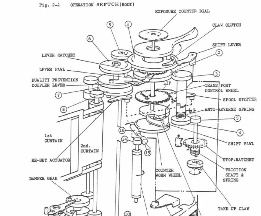
What a frame counter does—and does not—guarantee
The camera’s frame counter provides a record of the transport cycle. Coupling it to the winding mechanism helps the user distinguish a frame that has been advanced from one that has not. Interlocks may prevent another winding stroke before an exposure or prevent a second ordinary shutter release on the same frame. Advancing can also cock the shutter. The exact coupling varies by camera; a displayed number is an indicator of mechanism state, not a measurement of emulsion position at the gate.
The camera manual below documents a particularly instructive exception. Its multiple-exposure control allows the shutter to be recocked without advancing the film, and its counter waits until the film actually advances. The manual also warns that slack or forceful winding can shift the frame slightly—evidence that “same frame” does not imply mathematically exact in-plane registration.
Read the manual’s operating account to see how winding, shutter preparation, and frame counting are coupled—and deliberately decoupled for a multiple exposure.
In “Film Advance and Shutter Release,” find the paragraph beginning “After shutter release, the mirror and diaphragm automatically reset.” Read the winding sequence through its account of the counter. Then go to “Multiple Exposures” (pp. 72–73): starting with “After making the first exposure,” read the exception. Pay particular attention to what stays stationary, what is recocked, and the stated sources of slight frame movement.
A counter thus prevents bookkeeping errors only insofar as its coupling and the loading procedure are correct. If a strip fails to engage the take-up spool, a control may move while film does not travel as intended. If the film slips or is loaded with the wrong starting position, the displayed count cannot repair the lost spacing. Conversely, the multi-sheet holder shown earlier counts a change of which sheet is presented, rather than measuring a length of film moved through a gate. Both are frame counters, but they observe different transport events.
Conclusion
Reliable photographic registration depends on a chain of references. A plate or sheet holder locates a relatively rigid recording surface relative to the camera; a roll-film gate and pressure plate constrain a flexible strip without preventing it from moving; a winding system brings unused material into place; and a counter reports the progress of that mechanism. Flatness at the emulsion and correct frame advance are separate requirements, and a counter is not a substitute for either.
Next, we will examine a different alignment problem: how view cameras, rangefinders, twin-lens reflex cameras, and single-lens reflex cameras let the photographer judge framing and focus relative to the image that actually reaches the recording plane.