Recommended resources
The freely available resources this lesson will direct you to.
- How Image Stabilization & Camera Stabilization Workswww.youtube.com
- The INSIDE story on Image Stabilization: Gyros and coils and magnets, oh my!www.youtube.com
- WhitePaper_draft_ver.1.2_(HI_RES)www.st.com
- US20240377651A1 - Camera With Sensor Shift Tilt Actuator Arrangement - Google Patentspatents.google.com
Hello. Last lesson followed an autofocus measurement through to a lens-position command. Stabilization poses a related control problem, but the target is different: keep a stationary scene’s image nearly fixed relative to the recording surface while the camera moves during an exposure. Moving the sensor or a lens group can accomplish this without refocusing the scene.
This lesson connects measured camera motion to image displacement, then compares lens-shift and sensor-shift correction. We will also examine why position feedback, actuator response, and motion that varies across the scene limit the result. Allow about 40–45 minutes, including the selected resources.
What camera motion does to the image
A photograph integrates light over the time the shutter is open. If the projection of a stationary point moves across the sensor during that interval, the recorded point spreads along its path. The first distinction is therefore between camera motion and the image motion it causes.
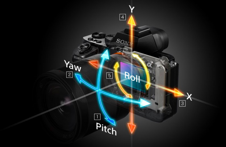
The cutaway below identifies five motions a stabilization system may address. Pitch and yaw change where the camera points; roll rotates it about the optical axis; X and Y are translations across that axis. These are motions of the camera, not five independently moving images.
For a thin lens focused on a subject at distance , recall the image distance
Suppose a small yaw angle rotates the camera about a point near its entrance pupil. With one consistent image-coordinate convention, a stationary subject’s projected position changes approximately by
For a distant subject, is approximately . This is the crucial scale conversion: a given angular shake produces more image travel with a longer focal length. If and the camera turns through degree during an exposure, the projection travels about —roughly 22 pitches on a sensor with pixels. That is image travel, not a prediction that every exposure will have an identical blur width; the motion’s timing matters too.
The manufacturer technical note Optical Image Stabilization (OIS) – White Paper illustrates the exposure-time problem. Read its diagrams as simplified models, not as a claim that a real handheld camera follows a straight-line path.
WhitePaper_draft_ver.1.2_(HI_RES)
Read Section 4, “OIS: the working principle and the specification,” for its comparison of an uncompensated and a compensated exposure.
On printed pp. 5–6, begin with the paragraph opening “In contrast to DIS” and read the blur argument through the paragraph following Figure 6. Focus on what changes during the shutter interval, and on the distinction made at Figure 7 between camera shake and scene motion. Treat the diagrams as illustrations of the principle rather than measured performance.
We can state the principle more precisely. Let be the image position without shake, let be the shake-induced displacement of that projection, and let be the sensor’s displacement in the same image-plane coordinate system. The point lands at sensor-relative position
A sensor-shift mechanism seeks . The sensor tracks the moving projection; it does not necessarily move opposite to the projection. A particular diagram may show the sensor moving “opposite” to a camera rotation because a rotating camera and its projected image move in opposite directions. Keeping those reference frames separate prevents a common sign error.
For an approximately stationary scene, the exposure is an average of differently displaced images. If is the sharp image and is the residual displacement, a one-dimensional model is
Successful stabilization makes small throughout the exposure. It need not hold the camera itself still. Nor is returning to the initial position by the end sufficient: a camera can trace a wide path and finish where it started, leaving a blurred exposure.
Two ways to counter the projection’s motion
Sensor-shift stabilization changes : a movable sensor follows the image formed by a comparatively fixed lens. Lens-shift optical stabilization changes the optical path instead: a movable lens group deflects the image toward a fixed sensor. Both attempt to reduce the same relative motion at the recording surface, but their required actuator travels are not interchangeable.
For a lens-shift group displaced by , write its image-plane effect locally as , where depends on the optical design, focus setting, and potentially field position. If both mechanisms are available, their shared target is
The sign of depends on which group moves and how image position is defined; it must be calibrated. This equation also shows why two mechanisms cannot simply receive independent commands to “correct all the shake.” Their combined effect must cancel the measured projection motion.
Watch these short selections from imagingresource’s The INSIDE story on Image Stabilization: Gyros and coils and magnets, oh my! for the physical distinction and a view of a movable sensor assembly. The footage is useful for visualizing hardware; we will use the control model below for precise statements about how it behaves.
The INSIDE story on Image Stabilization: Gyros and coils and magnets, oh my!
The video contrasts moving the imaging sensor with deflecting light using a movable lens group, then shows a voice-coil-driven sensor assembly.
Watch the two approaches for their common image-plane goal. Skip to combined correction for why lens and body mechanisms must be coordinated. Then watch the actuator and the lens version, concentrating on which part moves in each design.
In a voice-coil actuator, current in a coil placed in a magnetic field produces a force. A compliant suspension permits the intended motion while constraining unwanted tilt or displacement. The actuator’s force does not, by itself, guarantee a particular final position: mass, suspension stiffness, damping, gravity, and transients matter.
For a concrete sensor-shift construction, the following patent disclosure describes a sensor carried by a flexure. It documents a proposed mechanism, not independent evidence of its performance or proof that every camera uses this arrangement.
US20240377651A1 - Camera With Sensor Shift Tilt Actuator Arrangement - Google Patents
Read the description accompanying Figures 8A–8B to see how a movable sensor can be supported without leaving it mechanically unconstrained.
In the “DETAILED DESCRIPTION,” find the paragraphs immediately after the introduction to Figures 8A–8B. Read the flexure description. Identify the stationary outer frame, moving inner frame, and arms; focus on the competing requirements for stiffness and compliance, rather than the patent’s broader claims about benefits.
A two-axis lens-shift module usually corrects image translation caused by pitch and yaw. A sensor assembly that can translate and rotate in its plane can additionally address roll. Roll differs geometrically from pitch or yaw: for a small roll angle , the displacement at image coordinate is approximately
The displacement changes direction across the frame and vanishes at the rotation centre. One uniform lateral shift cannot cancel it everywhere; rotating the sensor can.
The five-axis classification also includes camera translation. If the camera moves laterally by , a subject at distance has an approximate additional image displacement proportional to . It is usually less important than angular shake for distant subjects, but becomes significant close up. Because its size depends on , one sensor translation cannot perfectly stabilize subjects at different depths simultaneously. A gyroscope senses angular rate, not this lateral translation; correcting the latter requires additional motion information or estimates. “Five-axis” consequently describes correction capabilities, not a guarantee that every kind of motion in every scene disappears.
Measuring motion is not the same as completing correction
To command a correction, the camera first estimates how it has moved. A gyroscope measures angular rate. Integrating a measured yaw rate gives a relative angle; the optical calibration then converts that angle to an expected image displacement. A sensor-position detector, by contrast, reports where the movable part actually went. These measurements answer different questions.
The white paper’s Sections 5 and 6 describe a lens-shift example with voice-coil motors and Hall-effect position sensors. It is one implementation rather than a universal camera architecture.
WhitePaper_draft_ver.1.2_(HI_RES)
Continue with the module architectures and control loop. Track the distinction between a measurement of camera rotation and a measurement of lens-group position.
In Section 5, “OIS camera-module technology,” on printed pp. 8–9, read the two mechanisms through Figure 9. Later in that section, on printed pp. 9–10, read the axis discussion through its explanation of roll. In Section 6, “OIS Architecture description,” on printed pp. 11–12, read the feedback description alongside Figure 14. Finally, in Section 6.4, “Control Algorithm,” on printed pp. 14–15, read the firmware sequence for the order of sensing, filtering, integration, and commanding.

In the diagram, the gyroscope does not directly verify that the lens group arrived at its target. The Hall sensors supply that feedback. Conversely, a Hall sensor cannot tell whether the camera is shaking: it senses the movable assembly relative to its housing. The controller compares a calibrated target position with the measured one, drives the coils, and repeats. Where motion along one mechanical axis also perturbs the other, the two nominally separate loops need cross-axis calibration.
Several limitations follow directly from this arrangement:
- Gyro bias and noise. Integrating a small constant rate error accumulates a false angle. Filtering and recentring help, but very slow drift cannot be followed indefinitely as though it were useful shake correction.
- Delay and finite bandwidth. Sensing, computation, and mechanical travel take time. For a sinusoidal image displacement of amplitude and angular frequency , a pure correction delay leaves a residual amplitude of approximately when is small. Faster shake is therefore harder to cancel even if its amplitude is unchanged.
- Finite travel and settling. An actuator can run out of stroke or oscillate after a command. Since angular image displacement scales approximately with for distant scenes, long focal lengths demand more image-plane correction for the same turn of the camera.
- Optical calibration. Moving a real lens group may change image quality or yield a field-dependent displacement. Feedback on its mechanical position ensures it followed a command, not that every image point is perfectly registered.
These are reasons to judge a stabilizer by residual blur under specified conditions, rather than by its number of axes alone. A quoted benefit of exposure “stops” means a shutter time times longer at some stated sharpness criterion and test conditions; it is not a universal promise for every focal length, subject, or pattern of shake.
Finally, stabilization addresses camera-induced image motion. A moving subject still changes position during the exposure, and neither a tracking sensor nor a deflecting lens group can generally hold all independently moving subjects fixed. Image shift during video can also be reduced electronically by cropping and repositioning successive frames, but that is distinct from keeping photons registered on the sensor during one exposure.
Conclusion
The governing quantity is residual projection motion relative to the recording surface. Pitch and yaw usually shift the whole image approximately together; roll rotates it across the field; camera translation matters increasingly at close distances. Lens-shift systems redirect the projection, while sensor-shift systems move the recording surface to follow it. Gyroscopes estimate angular motion, position sensors report actuator motion, and calibration connects both to the image-plane correction.
The next lesson turns from correcting motion in operation to allocating mechanical tolerances: how accurately must a camera place and align its parts so that focus, shutter timing, and image registration remain within specification at an acceptable manufacturing cost?