Recommended resources
The freely available resources this lesson will direct you to.
- Mermaid JS: Finally There's A Great UML & Diagram Drawing Toolwww.youtube.com
- Mermaid In Markdown, Diagrams As Code: Introduction, How-to, And Demowww.youtube.com
- Mermaid.js Tutorial: Flowcharts, Sequence Diagrams & Syntax Guide (2026)blog.starmorph.com
- Learn Mermaid.js - SimpleMermaidsimplemermaid.com
In our previous lesson, we explored how to adapt Mermaid's flowcharts to create approximations of UML use case diagrams. You learned to represent actors, use cases, and system boundaries, and importantly, how to document the aspects of UML that Mermaid doesn't natively support. This was an exercise in pragmatic modeling.
Today, we continue with business workflows, but we shift from approximation to a much more direct and powerful translation. This lesson focuses on creating Mermaid workflows that express the core concepts of UML Activity Diagrams. Unlike use case diagrams, activity diagrams map almost perfectly to Mermaid's flowchart capabilities. Your goal will be to model process flows, complete with actions, decision points, branches, and final outcomes. For a developer, this is akin to visually scripting the logic of a function or a user interaction, a process you're likely very familiar with conceptually.
From UML Activity to Mermaid Flowchart
A UML Activity Diagram is designed to show the flow of control from one activity to another. It's a detailed look at the internal logic of a use case or business process.
Let's look at a classic example of a UML Activity Diagram for an e-commerce payment process.
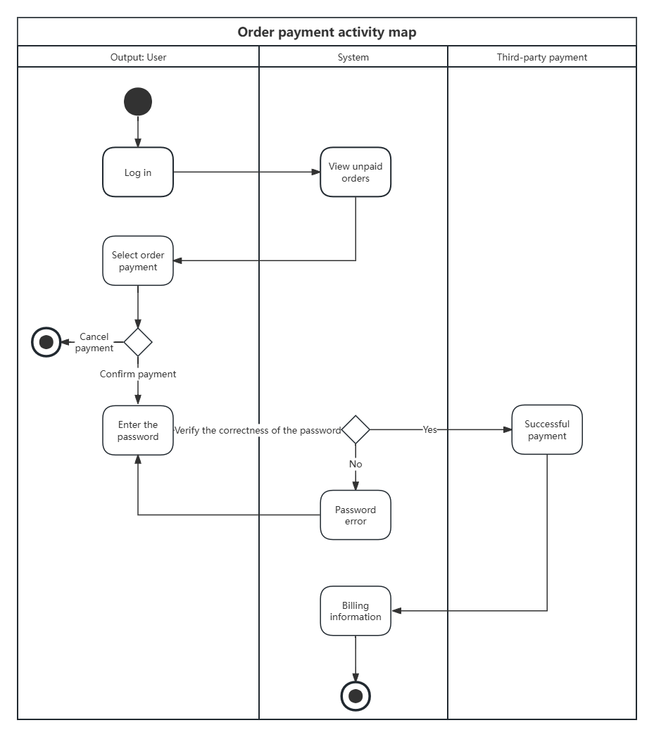
Our goal is to create diagrams with this level of detail and logical flow using Mermaid's flowchart syntax.
The Core Syntax for Workflows
The good news is that the mapping from UML activity concepts to Mermaid flowchart syntax is very intuitive.
- Initial & Final Nodes: In UML, these are a solid circle and a bullseye. In Mermaid, we often use rounded rectangle nodes
()or circle nodes(())to denote the start and end points of a flow. - Actions: These are the steps in the process. In UML, they are rounded rectangles. In Mermaid, we typically use the standard rectangle node
[]. - Decisions & Merges: These are critical for controlling the flow. A decision node (a diamond in UML) is where the path splits based on a condition. A merge node is where different paths reconverge. Mermaid uses the diamond shape
{}for this. - Flows/Edges: The arrows connecting the elements. In Mermaid, this is simply the
-->connector.
The SimpleMermaid and Starmorph resources provide excellent quick references for these shapes and connectors.
Learn Mermaid.js - SimpleMermaid
This guide provides a clear, concise table of node shapes and their common use cases, which is perfect for learning the basic vocabulary of Mermaid flowcharts.
Focus on the two tables in the guide. First, review the table of shapes, paying close attention to the syntax and suggested use case for Rectangles, Rounded Rectangles, and Diamonds. Then, look at the Connections & Arrows section to see how to create labeled connections, which are essential for decision branches.
Modeling a Real-World Flow
Theory is one thing, but seeing these elements combined to model a real process is where the concepts click. The following video by ArjanCodes provides a superb, developer-focused walkthrough of building a login workflow. He starts with a blank slate and progressively adds actions, decisions, and branches, explaining his reasoning along the way.
Mermaid JS: Finally There's A Great UML & Diagram Drawing Tool
Watch this segment from "Mermaid JS: Finally There's A Great UML & Diagram Drawing Tool" to see a practical demonstration of building a complete workflow.
The most valuable part is the detailed construction of the login flow. Watch from this section where the presenter builds the diagram step-by-step. Pay close attention to how he: Uses a diamond node {} for the "Is this an existing user?" check. Adds |Yes| and |No| labels to the arrows coming from the decision node to create branches. Creates a loop by having one path (Accept Conditions? --> No) go back to an earlier step. Merges two separate paths (Yes and No for existing user) into a single common step (Send email).
After watching this, you should have a solid grasp of how these simple syntax rules combine to describe complex logic. As the presenter notes, while you lose some granular control over layout compared to a GUI tool, the speed of "diagrams as code" is a massive advantage for development documentation.
Structuring Workflows with Subgraphs (Swimlanes)
Remember the vertical lanes in the UML Activity Diagram at the beginning? Those are called swimlanes, and they are used to partition the diagram to show who or what is responsible for each action. This is extremely useful for visualizing interactions between a user, a front-end system, a back-end API, and a database.
In Mermaid, we can achieve the same effect using subgraph. You've seen subgraphs before in the context of system boundaries, and here we use them to create visual containers for different actors or components in a single workflow.
Mermaid.js Tutorial: Flowcharts, Sequence Diagrams & Syntax Guide (2026)
This section of the Starmorph tutorial provides a clear example of using subgraphs to model a CI/CD pipeline, showing how different stages of a process can be visually grouped.
Find the section on "Subgraphs" and study the provided code example. Focus on how it uses the subgraph and end keywords to group related nodes, and how an arrow C --> D is used to connect nodes in different subgraphs. The syntax is this block here.
Practice: Modeling a Payment Workflow
Let's put all this together. Your task is to create a Mermaid flowchart that models the following simplified payment verification process. This will require you to use start/end nodes, actions, at least one decision with branches, and a merge.
Scenario:
A user has initiated a checkout and needs to provide payment.
- The flow starts.
- The system prompts the user to Choose Payment Method.
- The system then Checks if Card is on File.
- This is a decision point:
- If Yes, the flow proceeds directly to Confirm Payment.
- If No, the user must first Enter Card Details, and then the flow proceeds to Confirm Payment (the paths merge here).
- After the user confirms payment, the system will Process Payment.
- The flow ends with a Payment Complete status.
Try to build this diagram yourself in a text editor or the Mermaid Live Editor. Think about which shapes to use for each step and how to label the decision branches.
Click to see the solution
Here is one possible implementation of the workflow. Note how the No path goes to an extra step before merging back into the main flow at the Confirm_Payment node.
Conclusion
In this lesson, you've learned how to translate the concepts of UML Activity Diagrams into concrete Mermaid flowcharts. This is a fundamental skill for documenting any kind of process, from user interactions in a UI to back-end logic in an API.
The key takeaways are:
- Mermaid's
flowchartis the ideal tool for modeling workflows, directly mapping to UML Activity Diagram concepts. - Actions are represented by rectangle nodes
[], while decisions use diamond nodes{}. - Branches are created by adding text labels like
|Yes|or|No|to the arrows exiting a decision node. - Paths can merge by simply pointing arrows from different branches to the same subsequent node.
- Subgraphs can be used to represent UML swimlanes, partitioning a workflow to show which actor or system component is responsible for each step.
This lesson concludes our module on requirements and business workflows. We have covered how to model a system's high-level purpose with use cases and its detailed internal logic with activities. In our next lesson, we will pivot from modeling behavior to modeling structure. We'll begin exploring UML Class Diagrams, which allow us to define the "blueprints" of the objects and components that make up a system.