Recommended resources
The freely available resources this lesson will direct you to.
Hello! Welcome to your eighth lesson in the module on Quantum Error Correction Fundamentals.
In our last lesson, we designed and implemented the circuits for syndrome measurement in the 9-qubit Shor code. We saw how to use eight ancilla qubits to measure the eigenvalues of the eight stabilizer generators, producing an 8-bit syndrome string that fingerprints the error that has occurred.
Today, we will complete the quantum error correction loop. Our learning outcome is to use the extracted syndrome to implement the decoding logic and correction operations for the 9-qubit Shor code, recovering the logical state from a single-qubit Pauli error. We will translate the syndrome string into a diagnosis and then apply the appropriate quantum gate to fix the error.
1. From Syndrome to Diagnosis: The Decoding Logic
The process of decoding is a classical one. It takes the 8-bit syndrome, which we'll denote as , and maps it to a specific error and location. Since the Shor code is designed to correct any single-qubit Pauli error, our decoder needs to identify which of the possible errors ( for ) has occurred.
The decoding logic elegantly splits into two independent parts: one for bit-flips (X-type errors) and one for phase-flips (Z-type errors).
1.1 Diagnosing Bit-Flip Errors
The first six syndrome bits, through , are used to diagnose bit-flips. These bits correspond to the measurements of the -type stabilizers.
Let's focus on the first block of three qubits (0, 1, 2). Their bit-flip syndromes are determined by and , corresponding to syndrome bits and . An error flips a syndrome bit if it anti-commutes with the corresponding generator.
- No Error: All generators commute. Syndrome for this block:
00. - Error : Anti-commutes with but commutes with . Syndrome:
10. - Error : Anti-commutes with both and . Syndrome:
11. - Error : Commutes with but anti-commutes with . Syndrome:
01.
This gives us a simple lookup table. The same logic applies to the other two blocks:
- Block 2 (qubits 3, 4, 5): Syndrome bits diagnose .
- Block 3 (qubits 6, 7, 8): Syndrome bits diagnose .
The following lecture notes provide useful tables summarizing exactly these mappings.
PHY265 Lecture notes: Introducing Quantum Error Correction
These lecture notes on Quantum Error Correction by Alice Quillen provide clear, detailed tables for the Shor code's syndrome measurements.
Please review the tables titled 'Syndrome for bit flip errors in the 9-bit code' in Section 3.1 and the more extensive table at the beginning of Section 5.8. These tables explicitly list the syndrome patterns for single-qubit errors and are the basis for the classical decoding logic you will implement.
1.2 Diagnosing Phase-Flip Errors
The last two syndrome bits, and , diagnose phase-flips. They correspond to the generators:
A phase error will anti-commute with a generator if that generator contains an term.
- No Error: Syndrome
00. - Phase error in Block 1 (qubits 0,1,2): Any of will anti-commute with but commute with . Syndrome:
10. - Phase error in Block 2 (qubits 3,4,5): Any of will anti-commute with both and . Syndrome:
11. - Phase error in Block 3 (qubits 6,7,8): Any of will anti-commute with but commute with . Syndrome:
01.
This tells us which block has a phase error, but not which specific qubit. Fortunately, we don't need to know. As we saw when constructing the code, the logical states are built from cat states like . Notice that . The action of a Z-gate is identical regardless of which qubit in the block it acts upon. Therefore, to correct a phase error in a block, we can apply a gate to any qubit in that block (e.g., the first one by convention).
John Preskill's notes offer a concise explanation of this principle.
Chapter 7 Quantum Error Correction
In his definitive lecture notes on Quantum Computation, John Preskill explains the diagnosis and correction procedure for both bit-flip and phase-flip errors.
Please read Section 7.1, starting from 'Suppose that an unknown quantum state...' to the end of the paragraph beginning 'A three-qubit code would suffice...'. This covers the logic for diagnosing and correcting both bit-flip (using Z-type stabilizers) and phase-flip (using X-type stabilizers) errors, including the critical point about why applying Z to any qubit in an affected cluster is sufficient for correction.
1.3 Handling Y Errors
What about a error? Since , a error is equivalent to an error and a error occurring on the same qubit. The resulting syndrome will simply be the bitwise XOR of the individual and syndromes.
For example, a error:
- The component gives a bit-flip syndrome of
001100(from ). - The component gives a phase-flip syndrome of
11(from ). - The full syndrome for is
00110011.
Our decoder can handle this naturally. The bit-flip part of the syndrome (001100) points to an X-correction on qubit 4. The phase-flip part (11) points to a Z-correction on block 2 (qubits 3,4,5). A combined correction would be and (or or ). To correct the error, we should apply a operation. Ignoring the global phase, the correction is . So, our decoder works perfectly: it correctly identifies the need for an X-correction on qubit 4 and a Z-correction on the same qubit.
2. The Correction Operation
After the classical decoder has determined the required correction (e.g., "apply X to qubit 4"), the final step is to apply that quantum gate to the data qubits. In a real quantum computer, this would be a classically-controlled quantum operation: the quantum computer would execute a specific gate based on the classical syndrome measurement results.
The complete error correction cycle is illustrated in the circuit diagram below.
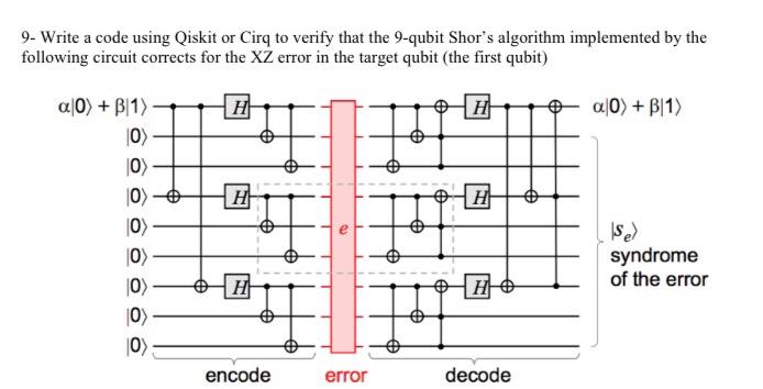
Your Task: Implementing the Decoder and Corrector
Building on your work from the last lesson, your task is to implement the full decoding and correction logic.
-
Create a Decoder Function: Write a classical Python function, for example
decode_shor_syndrome(syndrome), that takes an 8-bit syndrome string (e.g.,'00110011') as input. This function should return the necessary correction operation, such as a tuple('Y', 4).- This function should have two parts: one that looks at the first 6 bits to determine the bit-flip error and its location, and another that looks at the last 2 bits to determine the phase-flip error and its block.
- Combine the results. If you detect an X-error on qubit
iand a Z-error on the block containingi, the total error isYon qubiti.
-
Integrate into a Simulation: Create a full simulation pipeline in Qiskit or Cirq.
- Start with a 10-qubit register (1 for data, 9 for the code... wait, that's not right. 9 data qubits, 8 ancilla qubits for syndrome measurement, and 1 qubit for the initial state to be encoded). You will need 1 for the logical qubit, 8 for its encoded version (9 total data qubits), plus 8 ancilla qubits. Let's say we have 9 data qubits and 8 ancilla qubits.
- Encode: Prepare an arbitrary logical state, e.g., , and run it through your encoding circuit from the last lesson to produce on 9 qubits.
- Inject Error: Apply a single-qubit Pauli gate (, , or ) to one of the 9 data qubits.
- Measure Syndrome: Run your syndrome measurement circuit from the last lesson, measuring the 8 ancillas into a classical register.
- Decode and Correct: In your simulation, retrieve the classical syndrome string. Pass it to your
decode_shor_syndromefunction to get the correction operation. Apply this correction gate to the data qubits. - Verify: How do you know if it worked? The 9 data qubits should now be back in the state , up to a global phase. The simplest way to verify this in a statevector simulation is to compare the statevector after correction to the statevector immediately after encoding (before the error). They should be identical (or differ by a phase factor of -1 or ). Alternatively, you can apply the inverse of the encoding circuit and check if you recover the original state on the first qubit.
Test your understanding!
You run your syndrome measurement circuit and obtain the syndrome 00000010. What does your decode_shor_syndrome function output, and what correction gate do you apply?
Show answer
- Syndrome:
00000010 - Bit-flip part (
s0..s5):000000. This indicates no bit-flip error. - Phase-flip part (
s6s7):10. This indicates a phase-flip error in Block 1 (qubits 0, 1, 2). - Decoder Output:
('Z', 0)(or 1, or 2, by convention we choose the first). - Correction Gate: Apply a
Zgate to qubit 0.
This implementation task directly addresses the learning outcome by requiring you to build the bridge from the abstract syndrome to the concrete recovery operation. Given your experience with building simulations from scratch, structuring this classical-quantum workflow should be a satisfying challenge.
Conclusion
Today, we closed the loop on quantum error correction with the 9-qubit Shor code. We've seen how a classical algorithm—the decoder—can interpret a quantum measurement—the syndrome—to diagnose an error and trigger a corrective quantum operation.
Key Takeaways:
- Decoding the Shor code syndrome is a classical process that can be broken down into diagnosing bit-flips (using the first 6 syndrome bits) and phase-flips (using the last 2 bits).
- A bit-flip syndrome identifies the precise qubit that flipped. A phase-flip syndrome identifies the 3-qubit block that suffered the error.
- Correcting a phase-flip in a block can be done by applying a gate to any single qubit within that block.
- errors manifest as a combination of bit-flip and phase-flip syndromes, and are corrected by applying both and gates to the affected qubit.
- The full QEC procedure is a cycle: Encode Error Detect (Syndrome Measurement) Decode (Classical Logic) Correct (Quantum Gate).
Preview of the next module:
We have successfully built a code that can correct single-qubit errors. However, our analysis assumed that the gates used for encoding, syndrome measurement, and correction are themselves perfect. What happens when these operations are also noisy? This is the domain of fault-tolerant quantum computing. In our next lesson, we will begin exploring this crucial topic by distinguishing between Clifford gates, which are "easy" to simulate classically and form the backbone of many error correction schemes, and non-Clifford gates, which provide full quantum computational power but are harder to implement fault-tolerantly.