Recommended resources
The freely available resources this lesson will direct you to.
Hello! Welcome back to your course on building a secure ThinkPad.
In the first module, we laid the conceptual groundwork for security, defining what a threat model is and establishing the importance of minimizing the Trusted Computing Base (TCB). We are now ready to apply these principles to the machine itself, starting at the most fundamental layer.
This lesson is the first in our second module, "Firmware Security: Theory and Principles." Our goal is to explain the role of the BIOS/UEFI in the computer's boot sequence. Understanding this process is the first step toward appreciating why the default, proprietary firmware on your x230 is a security concern and why we're going to replace it.
This lesson should take you about 60 minutes to complete.
1. From Power Button to Operating System: The Role of Firmware
When you press the power button on a computer, what actually happens? The processor can't just start running your operating system. The hardware—CPU, RAM, disk drives—is inert. It needs to be initialized, tested, and configured before it can do anything useful. This is the job of the firmware.
Firmware is a special class of software permanently stored on a memory chip on the motherboard. It's the critical link between the hardware and the operating system. For a quick and clear overview of what firmware is and what it does, please watch the following short video.
As the video explains, the original firmware standard for PCs was the BIOS (Basic Input/Output System). For decades, it followed a straightforward sequence:
- Power-On Self-Test (POST): The BIOS runs a series of checks to make sure the essential hardware (CPU, RAM, video card) is present and functional. You might hear a single beep if all is well, or a sequence of beeps if there's an error.
- Device Initialization: It initializes the hardware it has detected.
- Boot Device Selection: The BIOS checks storage devices (hard drive, USB drive, etc.) in a pre-configured order.
- Handoff: It reads the first 512 bytes of the first bootable device—the Master Boot Record (MBR)—and executes the code it finds there. This code is the first stage of the operating system's bootloader, which then takes over.
This entire process is a handoff of control, starting with the BIOS. This diagram illustrates the classic BIOS/MBR boot sequence.

This flowchart shows the traditional boot sequence. Control passes from the BIOS to the Master Boot Record (MBR) on the hard disk, then to the boot sector of the active partition, and finally to the operating system's bootloader.
2. The Modern Successor: UEFI
The traditional BIOS served its purpose for decades, but it had significant limitations, such as being unable to boot from drives larger than ~2.2 TB. To address this and other issues, the industry developed a modern replacement: UEFI (Unified Extensible Firmware Interface).
UEFI isn't just an updated BIOS; it's a fundamentally different and more powerful system. Think of it less as a simple ignition sequence and more as a miniature operating system that prepares the machine for the main OS.
To understand the key differences and advantages of UEFI, please watch the rest of the Techquickie video and a second video that clearly contrasts the two systems.
-
Action: Watch the remainder of
. -
Action: Watch the first three and a half minutes of the following video, which explains how BIOS and UEFI locate the bootloader differently and summarizes their key differences.
As you've seen, UEFI is more sophisticated. It has a graphical interface, networking capabilities, and its own driver model. Instead of the MBR, it uses the GUID Partition Table (GPT), which allows for vastly larger disks and more partitions. The boot process is also different: UEFI doesn't just execute the first sector of a disk. It actively looks for a specific bootloader file (e.g., \EFI\BOOT\BOOTX64.EFI) in a dedicated EFI System Partition (ESP).
This diagram shows the simplified UEFI boot flow:
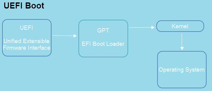
This flowchart illustrates the modern UEFI boot sequence. The UEFI firmware initializes the hardware and then directly loads and executes an EFI bootloader file from a specific partition on the disk, which in turn loads the operating system.
3. A Deeper Dive: The UEFI Boot Phases
The simple diagram above is useful, but given your background and our goal of modifying the firmware, it's worth understanding the UEFI boot process in more detail. It's not a single monolithic block of code; it's a structured, multi-phase process designed to build up the system's capabilities step-by-step.
This process is often called the "Platform Initialization" (PI) sequence. The article we'll use as a reference, "Understanding modern UEFI-based platform boot," is written from a security researcher's perspective and provides an excellent, detailed overview.
The True Beginning: The Root of Trust
Before we even get to the UEFI phases, it's crucial to understand where the process truly begins. On modern Intel systems, the first code to execute upon power-on is not on the main CPU. It's on a small, secondary processor inside the chipset—the Intel Converged Security and Manageability Engine (CSME), which we will discuss in depth in a future lesson.
This CSME code, baked into the chipset's silicon, acts as the hardware Root of Trust (RoT). It verifies and loads the first piece of firmware for the main CPU. This begins a "chain of trust," where each stage cryptographically verifies the next before executing it. This concept is the foundation of a secure boot process and directly relates to the Trusted Computing Base (TCB) we discussed in Module 1. The entire chain is only as strong as its first link—the RoT.
-
Action: Please read the "Pre-UEFI" and the first part of the "SEC" sections of the following article. Focus on the role of the CSME and the concept of the chain of trust.
Understanding modern UEFI-based platform boot (SEC Phase (Security Phase))
(Reading time: ~10 minutes)
The Main PI Phases
Once the Root of Trust has verified and started the initial CPU code, the main UEFI boot sequence begins. It consists of several distinct phases:
-
Action: Now, read through the descriptions of the SEC, PEI, DXE, and BDS phases in the same article. As you read, focus on the primary goal of each phase and how it builds upon the previous one.
Understanding modern UEFI-based platform boot (SEC Phase (Initial Boot Block); PEI Phase (Pre-EFI Initialization); DXE Phase (Driver eXecution Environment); BDS Phase (Boot Device Selection))
(Reading time: ~15 minutes)
Here is a summary of those phases to consolidate your understanding:
| Phase | Name | Primary Purpose | Analogy |
|---|---|---|---|
| SEC | SECurity | Establishes a minimal, temporary execution environment using the CPU cache as RAM (Cache-as-RAM or CAR). This is necessary because the main system memory (DRAM) is not yet available. | Waking up in a dark room and fumbling for the light switch. You have just enough awareness to perform one critical task. |
| PEI | Pre-EFI Initialization | Initializes the CPU, chipset, and most importantly, the main system memory (DRAM). It's a collection of small modules (PEIMs) that prepare the core hardware. | The lights are on. You can now see the room and start organizing it, setting up your workspace (main memory). |
| DXE | Driver eXecution Environment | The main phase. It loads a host of drivers for higher-level devices (storage, USB, network cards) and provides the key Boot Services and Runtime Services that the OS bootloader will use. Features like Secure Boot are implemented here. | The workshop is fully set up. All tools (drivers) are available, and the main project (booting the OS) can begin. |
| BDS | Boot Device Selection | Uses the services provided by DXE to read boot entries from NVRAM, find the EFI System Partition on the selected device, and load the OS bootloader (e.g., winload.efi, grubx64.efi). |
Following the blueprint to select the right components and start the final assembly. |
| TSL/RT | Transient System Load / RunTime | The OS bootloader takes control. It calls ExitBootServices() to terminate the UEFI boot services, but Runtime Services (for tasks like updating firmware variables or resetting the system) remain available to the running OS. |
The machine is assembled and running. The construction crew (Boot Services) has left, but a maintenance team (Runtime Services) remains on call. |
This phased approach is what makes UEFI so extensible. However, its complexity—with hundreds of individual modules from different vendors—also dramatically increases the attack surface compared to a simple legacy BIOS. This is a key motivation for replacing it with a minimal, open-source alternative.
4. Conclusion
In this lesson, we've dissected the computer's startup sequence, a process that is foundational to its security.
Key Takeaways:
- Firmware (BIOS/UEFI) is the first software to run, responsible for initializing hardware and handing control to the operating system.
- Legacy BIOS follows a simple process: POST, then execute the code in the Master Boot Record (MBR) of a bootable disk.
- Modern UEFI is a complex, phased "mini-OS" that initializes hardware in stages (SEC, PEI, DXE) before loading a specific bootloader file from a GPT disk.
- The boot process is built on a chain of trust that starts from a hardware Root of Trust (like the Intel ME). The integrity of this chain is paramount for system security.
Preview of the Next Lesson:
Now that you understand what the firmware does, we will explore why the proprietary, closed-source firmware that ships with most computers is a significant security risk. We'll discuss the problems of unauditable code, the history of firmware vulnerabilities, and why having a "black box" at the very foundation of your system is antithetical to our security goals. This will lead directly into our discussion of the Intel Management Engine and the case for Coreboot.