Recommended resources
The freely available resources this lesson will direct you to.
Hello! Welcome back to our course on radioelectronics.
In our last lesson, we explored the mathematical representation of Frequency Modulation (FM) and learned how to estimate its bandwidth using Carson's Rule. We saw that in an FM signal, the information is encoded in the instantaneous frequency of the carrier, , while the amplitude remains constant.
Today, we will address the crucial final step in the communication chain: recovering the original message signal from the modulated FM wave. This process is known as FM demodulation or FM detection. We will investigate two key methods for accomplishing this: the conceptually simple Slope Detector and the modern, high-performance Phase-Locked Loop (PLL).
1. The Principle of Frequency-to-Amplitude Conversion
The core challenge of FM demodulation is to create a circuit whose output voltage varies linearly with the input frequency. If we can achieve this, the output voltage will be a direct copy of the original message signal, . The simplest way to do this is to use a circuit that performs frequency-to-amplitude conversion, and then use a standard AM envelope detector to extract the message.
The Simple Slope Detector
The most basic circuit that can perform frequency-to-amplitude conversion is a simple LC resonant tank circuit, also known as a discriminator.
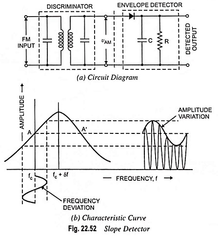
The principle of operation is as follows:
- The LC tank circuit is tuned so that its resonant frequency is slightly offset from the FM carrier frequency, . This means the carrier frequency sits on the "slope" of the resonance curve, as shown in part (b) of the image above.
- As the incoming signal's instantaneous frequency, , varies around , the impedance of the tank circuit changes.
- This change in impedance causes the voltage across the tank circuit to vary in amplitude, effectively converting the original frequency modulation into amplitude modulation (AM).
- This AM signal is then fed into a standard envelope detector (the diode and RC network), which recovers the envelope—our original message signal.
While simple, this method has significant drawbacks:
- Poor Linearity: The slope of the resonance curve is only approximately linear over a very small range. Any deviation outside this range results in distortion.
- Amplitude Sensitivity: The circuit is fundamentally an AM detector. Therefore, it is highly susceptible to any amplitude noise or variations in the incoming signal, which an ideal FM system should reject. This necessitates a "limiter" circuit before the detector to remove any amplitude variations.
To address these issues, a more refined version called the Balanced Slope Detector was developed.
FM DEMODULATORS FM Slope Detector
To understand how the limitations of the simple slope detector are addressed, let's look at the balanced slope detector. This resource explains its circuit and operation.
Please read the sections 'Balanced FM Slope Detector (Balanced Frequency Discriminator)' and 'Working Operation of the Circuit'. Focus on how the use of two detuned circuits (one above f_c and one below f_c) and the subtraction of their outputs creates a more linear characteristic and helps cancel unwanted effects. Also, note the summary of its drawbacks.
As you've read, the balanced slope detector uses two resonant circuits and takes the difference of their outputs. This creates a more linear "S-shaped" characteristic curve that is centered at the carrier frequency. While an improvement, it is still sensitive to amplitude noise and can be difficult to tune correctly. These limitations paved the way for more advanced techniques, which are now standard in modern electronics.
2. The Phase-Locked Loop (PLL) FM Demodulator
The Phase-Locked Loop (PLL) is a far more sophisticated and effective method for FM demodulation. It is a feedback control system that is ideal for implementation in integrated circuits (ICs), making it the dominant technology in modern radio receivers.
Block Diagram and Principle of Operation
A PLL consists of three main components connected in a feedback loop: a Phase Detector, a Loop Filter, and a Voltage-Controlled Oscillator (VCO).
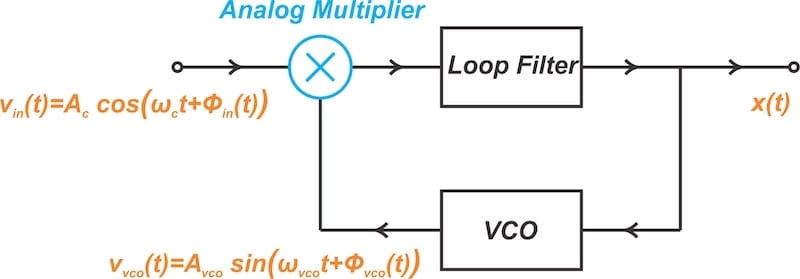
Here’s how it works to demodulate an FM signal:
- VCO: The Voltage-Controlled Oscillator generates a periodic signal whose frequency is determined by an input DC voltage. Its behavior is described by , where is its free-running frequency.
- Phase Detector: This component (often an analog multiplier) compares the incoming FM signal with the VCO's output signal. It produces an "error" signal whose voltage is proportional to the phase difference between the two signals.
- Loop Filter: This is a low-pass filter that removes any high-frequency components from the error signal, producing a clean DC or low-frequency voltage, .
- Feedback Action: This filtered voltage is fed back to the control input of the VCO.
The magic of the loop is in its continuous effort to minimize the phase error.
- When the incoming FM signal's frequency changes, a phase error develops.
- The phase detector and loop filter produce a corresponding control voltage .
- This voltage forces the VCO's frequency to change in a way that tracks the incoming signal's frequency, thereby reducing the phase error.
- In the "locked" state, the VCO frequency is forced to be exactly equal to the input frequency . For this to happen, the control voltage must be precisely the voltage needed to produce that frequency.
Since and , when the loop is locked ( and we set ), we get:
The output voltage is a scaled replica of the original message signal, . This is our demodulated signal!
Phase locked loop FM detector (PLL FM demodulator)
The following resource provides a more detailed look at the operation, performance, and design of PLL-based FM demodulators. It confirms the principles we've just discussed and explores the advantages of this approach.
Please read the following sections: 'PLL FM demodulation basics' to reinforce the core concept. Then, read 'PLL FM demodulator performance' to understand its key advantages. Finally, review 'Working Operation' and the 'Mathematical Explanation' to see how the feedback loop is formally described. Given your background, you should find the mathematical model quite accessible; focus on how the multiplier and low-pass filter work together to produce the error signal.
As the reading highlights, the PLL approach offers several major advantages that have made it a cornerstone of modern communication electronics:
- High Linearity: The linearity of the demodulation is determined by the voltage-to-frequency characteristic of the VCO, which can be designed to be extremely linear over the required range. This results in very low distortion.
- Excellent Noise Immunity: The PLL inherently tracks the frequency/phase of the signal and is largely insensitive to amplitude variations. This provides excellent rejection of AM noise.
- Ease of Integration: The entire PLL circuit can be easily fabricated on a single integrated circuit, drastically reducing manufacturing costs, size, and eliminating the need for bulky and expensive inductors or transformers found in older detector designs.
Conclusion
In this lesson, we have explored two distinct methods for demodulating FM signals. We started with the intuitive but flawed slope detector and progressed to the elegant and powerful Phase-Locked Loop.
Key Takeaways:
- FM demodulation is the process of converting the frequency variations of an FM signal back into a voltage that represents the original message signal.
- Slope detectors perform this by using a frequency-discriminating circuit (like a detuned LC tank) to convert frequency variations into amplitude variations, which are then detected by an envelope detector. They are simple but suffer from poor linearity and sensitivity to amplitude noise.
- The Phase-Locked Loop (PLL) is a superior feedback control system composed of a Phase Detector, Loop Filter, and Voltage-Controlled Oscillator (VCO).
- The PLL works by generating a signal that tracks the frequency of the input FM wave. The control voltage required to keep the VCO locked to the input frequency is a precise, low-distortion replica of the original modulating signal.
- Due to their high performance, noise immunity, and suitability for integrated circuits, PLLs are the standard for FM demodulation in modern receivers.
We have now covered the complete process for both AM and FM systems: modulation, bandwidth analysis, and demodulation. The next step is to understand how these radio signals travel through space. In our next lesson, we will begin our study of Antennas, starting with fundamental concepts like radiation patterns, gain, and impedance.