Recommended resources
The freely available resources this lesson will direct you to.
Hello! Welcome back to our course on radioelectronics.
In our last lesson, we laid the groundwork by defining the essential characteristics of sinusoidal signals: amplitude, frequency, period, and phase. We described them using the time-domain function . While this representation is accurate, performing operations like differentiation, integration, or even simple addition with phase-shifted signals can become mathematically tedious.
Introduction
Today's Goal: This lesson introduces a more powerful and elegant way to work with sinusoids. You will learn how to represent sinusoidal signals using complex exponentials (via Euler's formula) and a compact notation called phasors. This is the bridge from a descriptive understanding of AC signals to the powerful mathematical analysis used in engineering.
By the end of this lesson, you will understand how this complex number-based approach transforms the calculus of circuit analysis into straightforward algebra, a technique that is fundamental to radioelectronics. For you, this is the first major step into the "advanced math" part of your learning goal.
Time to complete: Approximately 50 minutes.
1. Why Bother with Complex Numbers?
In DC circuits with only resistors, voltage and current are always in phase. The math is simple. However, as we saw briefly, components like capacitors and inductors introduce a phase shift between voltage and current. Adding two sinusoids with different amplitudes and phases, like , requires cumbersome trigonometric identities. Imagine doing this for a complex circuit!
This is where complex numbers become an indispensable tool. Let's start with a video that beautifully explains the motivation.
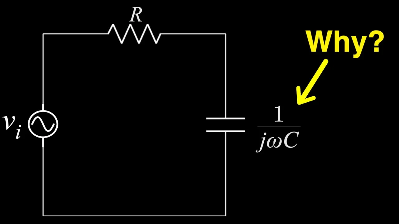
- Resource: by Zach Star
- Watch: 00:00 to 03:46
The video highlights two key ideas:
- The Problem: Phase shifts in AC circuits make the math difficult.
- The Solution: Euler's formula provides a way to represent sinusoids in a form that is much easier to manipulate.
As the video mentions, in electrical engineering, the imaginary unit is denoted by instead of to avoid confusion with the symbol for current, .
Euler's formula is the cornerstone of this method:
This elegant identity connects the exponential function to the trigonometric functions. From this, we can see that the cosine function is the real part of the complex exponential, and the sine function is the imaginary part.
By convention, engineers use the cosine function as the standard reference. Therefore, we can represent a real-world sinusoidal voltage as the real part of a complex exponential:
This might seem more complicated at first, but let's see the incredible simplification it brings to circuit analysis.
2. The Payoff: Turning Calculus into Algebra
The true power of this representation becomes apparent when we deal with capacitors and inductors, whose voltage-current relationships involve derivatives and integrals.
Let's return to the same video to see a practical application with a capacitor.
- Resource: by Zach Star
- Watch: 05:37 to 07:46
Here's the crucial insight explained in the video:
- Our complex voltage is . (We'll remember to take the real part at the end).
- The capacitor relationship is .
- Taking the derivative of our complex voltage is simple, thanks to the properties of the exponential function:
- Substituting this back into the capacitor equation gives us the complex current:
Notice what happened: the differential operator was replaced by simple multiplication by . We have transformed a calculus problem into an algebraic one! This is a profound simplification that makes analyzing even the most complex AC circuits manageable.
3. Formalizing the Phasor
In AC circuit analysis, all voltages and currents oscillate at the same source frequency, . This means the term is a common factor in all our equations. We can "suppress" this time-varying part during our calculations and reintroduce it only at the very end to get the final time-domain answer.
What's left is a complex number that represents the signal's amplitude and phase. This is called a phasor.
Let's watch a video that provides the formal definition and a helpful review of complex number representations.
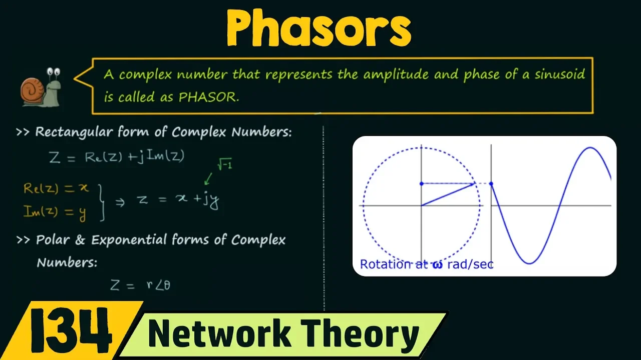
- Resource: by Neso Academy
- Sections to watch:
- Complex Number Review (02:05 - 07:02): A quick refresher on rectangular, polar, and exponential forms.
- Phasor Representation (07:02 - 10:34): This part formally derives the phasor from Euler's identity.
Let's summarize the derivation:
A time-domain signal:
Can be written using Euler's formula as:
The phasor is the part of this expression that contains the amplitude and phase information, with the time-varying part removed. It's typically written as a bold capital letter.
Phasors are complex numbers and can be expressed in two main forms:
- Polar Form: . This form is intuitive as it directly shows the peak amplitude () and phase angle ().
- Rectangular Form: , where and . This form is most useful for adding or subtracting phasors.
A phasor is a static representation of a dynamic signal—it's like a snapshot of the rotating vector at time .
4. Putting It All Together: From Sinusoid to Phasor
Let's practice the conversion. The key is to always use cosine as the reference.
Example 1: Convert V to its phasor form.
- The signal is already a cosine function.
- The amplitude is V.
- The phase is .
- The phasor is V.
Example 2: Convert A to its phasor form.
- The signal is a sine function. We must convert it to cosine using the identity .
- Now it's in the standard form. The amplitude is A.
- The phase is .
- The phasor is A.
As a final point, remember that phasor analysis is only valid when all signals in the circuit have the same frequency. If frequencies differ, you cannot use this simplified method. The final segment of the Neso Academy video makes this important point.
Conclusion
Excellent work! You've just learned one of the most powerful techniques in electrical engineering. By moving from the time domain to the frequency domain (or phasor domain), we've simplified our analysis toolkit dramatically.
Key Takeaways:
- Sinusoids can be represented as the real part of a complex exponential using Euler's formula: .
- This representation transforms differential and integral relationships into algebraic ones (e.g., ).
- A phasor is a complex number that captures the amplitude and phase of a sinusoid, written as . It is a "snapshot" of the signal at .
- Phasor analysis requires that all signals under consideration have the same frequency.
What's Next?
In our next lesson, "Complex Impedance: Representing R, L, and C in the Frequency Domain," we will use the phasor concept to define a generalized, frequency-dependent "resistance" for capacitors and inductors called impedance () . The Zach Star video gave a sneak peek of this with the capacitor's impedance being . This will allow us to analyze AC circuits using methods that look remarkably similar to Ohm's Law.