Recommended resources
The freely available resources this lesson will direct you to.
- ASIC Interview Questions | Process, Voltage and Temperature (PVT) Corner | On-chip Variationswww.youtube.com
- DVD - Lecture 5h: Multi-Mode Multi-Corner (MMMC)www.youtube.com
- Day 6: PVT Corners and MCMM — Process Voltage Temperature in STA | EcrioniX STA Courseecrionix.org
- Parasitic Interconnect Corner (RC Corner) - Part 2 |VLSI Conceptswww.vlsi-expert.com
Welcome back. Last lesson separated the netlist, SDC, Liberty library, technology data, and extracted parasitics by the questions each answers. There is one more choice behind a timing report: which version of the cell and wire behavior is being used, and which operating state the design is in.
In this lesson, you will distinguish PVT corners (conditions for cells), RC corners (conditions for interconnect), modes (how the design is operated), and analysis scenarios (the combinations the tool checks). Allow about 40 minutes, including the video segments.
PVT corners: which cell behavior applies?
A standard cell does not have one delay that applies to every manufactured chip and operating condition. Its transistors are affected by three dimensions:
- Process describes manufacturing variation in transistor characteristics. Common labels are SS (both NMOS and PMOS slow), TT (typical), and FF (both fast). SF and FS describe mixed NMOS/PMOS behavior.
- Voltage describes the supply at which the cell operates. Lower voltage generally reduces drive strength and increases delay; higher voltage generally does the opposite.
- Temperature also changes device behavior. Hotter conditions often increase cell delay, but that trend is not universal: in some technologies and voltage ranges, a cold condition can be slower.
A PVT corner specifies a combination, such as SS process, low voltage, hot temperature. Cell libraries are characterized for specified operating conditions, so the chosen corner determines which cell timing data the analysis uses. It affects more than combinational gates: flip-flop clock-to-Q delay and setup and hold requirements also depend on the characterized conditions.
Watch the selected portions of Flop_n_Adder’s ASIC Interview Questions | Process, Voltage and Temperature (PVT) Corner. Concentrate on the physical meaning of each variation, rather than treating the corner labels as definitions to memorize.
ASIC Interview Questions | Process, Voltage and Temperature (PVT) Corner | On-chip Variations
Flop_n_Adder explains process variation, supply voltage, library characterization, and the usual setup-versus-hold motivation for checking different PVT conditions.
Watch process and voltage for their effects on transistor speed, then corner labels for SS, FF, mixed-process corners, and characterized libraries. Finish with timing checks, which contrasts the conventional slow setup and fast hold conditions. Treat those conditions as useful starting points, not guaranteed worst cases for every technology or path.
The cube below pictures PVT as three dimensions rather than a single “speed” setting.
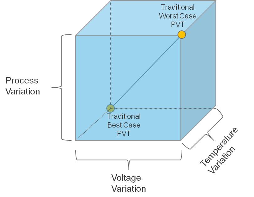
For setup, the concern is generally that data arrives too late. A slow cell condition is therefore an obvious place to look. For hold, the concern is generally that new data arrives too early, making a fast cell condition important. But “SS/low-voltage/hot is always worst for setup” and “FF/high-voltage/cold is always worst for hold” are too strong. Temperature inversion, the behavior of particular cell arcs, and the relative delays of data and clock paths can change which condition limits a check. Use the qualified corner set supplied for the technology and project.
A PVT corner primarily tells us about the cell timing model. It does not, by itself, specify the resistance and capacitance of the routed wires.
RC corners: which interconnect behavior applies?
Recall the AND gate and capture flip-flop from the previous lesson. Even if their logical connection stays the same, the wire between them can acquire different electrical characteristics under different interconnect manufacturing conditions. Wire width and thickness affect resistance; geometry and spacing affect capacitance, including capacitance to neighboring wires. Temperature can affect wire resistance as well.
An RC corner represents an assumed set of interconnect resistance and capacitance conditions used for estimation or parasitic extraction. Depending on the flow, you may encounter names such as Cmax/Cmin, RCmax/RCmin, or technology-specific extraction-corner names. The names are clues to the modeled behavior, not a promise that every net’s delay is maximized or minimized.
Why might more than one wire corner matter? On a short connection, the capacitance seen by a cell driver may have a strong effect on its transition and delay. On a long connection, wire resistance and distributed capacitance can contribute substantially to delay. Consequently, the condition that is most pessimistic for one path need not be most pessimistic for another. Resistance and capacitance also arise from related geometry; you should not assume that an “RCmax” file simply combines independently chosen maximum values of every quantity.
Keep the two meanings of process separate. SS and FF describe transistor-process conditions represented in cell characterization. An RC corner describes interconnect conditions. Both reflect manufacturing and operating variation, but they are different inputs to timing analysis. A flow associates an appropriate cell-library condition and interconnect condition when it constructs a corner for analysis. After routing, that interconnect condition may be represented by parasitics extracted for the design; the resulting SPEF still has to match the netlist being analyzed.
Modes: what is the chip doing?
Conditions alone do not specify the timing requirement. The same manufactured chip may operate in different ways. In functional mode, it may run its normal application clocks. In scan test mode, test controls select scan paths and a different clock arrangement or frequency may apply. Other designs may have performance and low-power modes with different clocks, enabled logic, or supply arrangements.
A mode describes such an intended operating state and its applicable constraints. Its SDC configuration can specify clocks, interface delays, and justified mode-dependent assumptions—for example, the value of a test-enable signal. A mode is therefore not another name for a PVT corner: functional and scan modes can each need analysis at several cell and wire conditions.
This distinction prevents a common mistake. Checking scan paths against functional-mode assumptions may analyze the wrong active paths or clock relationships. Conversely, giving scan mode a slower clock does not automatically make every scan check safe; the relevant paths and constraints must still be checked.
Adi Teman’s DVD - Lecture 5h: Multi-Mode Multi-Corner (MMMC) shows why teams organize these choices into analysis views. The lecture uses particular tool terminology and examples; focus here on the relationships, not command syntax.
DVD - Lecture 5h: Multi-Mode Multi-Corner (MMMC)
Adi Teman develops the idea of an analysis view from operating modes, timing libraries, and interconnect extraction conditions. Watch to connect the distinctions in this lesson to a physical-design tool configuration.
Start with multiple conditions to see why one assumed worst case is insufficient. Watch analysis views for examples combining a mode and a corner. In mode definitions, notice the SDC-based constraint mode and the separate delay corner. Then use corner ingredients to distinguish library sets from RC extraction data, and the summary to review how the pieces fit together. Do not treat the lecture’s illustrative corner choices as a universal signoff recipe.
Analysis scenarios: putting the choices together
An analysis scenario—often called an analysis view in tool documentation—combines an operating mode with a delay corner and specifies the checks to perform. For our purposes, a delay corner brings together the selected cell timing condition (PVT-characterized libraries) and interconnect condition (RC data). Tool-specific structures can be more detailed, but this is the distinction to retain.
Imagine a small block with a 1 ns functional clock and a separate 10 ns scan clock. The following is an illustrative starting matrix, not a complete signoff plan:
| Scenario | Mode and constraint intent | Cell and interconnect conditions | Check emphasized |
|---|---|---|---|
func_slow |
Functional, 1 ns clock | Slow-cell PVT with a selected late-path RC corner | Setup |
func_fast |
Functional, 1 ns clock | Fast-cell PVT with a selected early-path RC corner | Hold |
scan_slow |
Scan, 10 ns clock and scan controls | Slow-cell PVT with a selected late-path RC corner | Setup |
scan_fast |
Scan, 10 ns clock and scan controls | Fast-cell PVT with a selected early-path RC corner | Hold |
This matrix demonstrates multi-corner multi-mode analysis, often abbreviated MCMM or MMMC. It does not say that only four checks are ever required. A project may check setup and hold in additional corner combinations because the worst cell-and-wire combination is path-dependent. The scenarios must also reflect operating combinations the product can actually encounter.
When reading a report labeled with a scenario name, unpack it into separate questions:
- Mode: Which clocks, active paths, and SDC assumptions apply?
- Cell condition: Which PVT-characterized libraries supply cell delays and timing requirements?
- Wire condition: Which RC extraction assumptions or corresponding parasitics supply interconnect behavior?
- Check: Is this an early-arrival/hold concern, a late-arrival/setup concern, or another analysis?
That habit is useful in a physical-design role. “The path passes” is incomplete unless you know under which scenario it passes. A design clean at nominal TT conditions may still fail an applicable slow or fast condition; a result obtained with the wrong mode or mismatched parasitics may be misleading even if its reported slack looks comfortable.
Key takeaways
PVT corners select operating conditions for cell characterization; RC corners model interconnect variation; modes specify how the design operates and which constraints apply. An analysis scenario joins a mode with the relevant cell-and-wire corner so a particular timing check has a defined meaning. Neither one “worst” PVT point nor one “worst” RC file can automatically stand in for every path and check.
Next, you will move from these analysis concepts to practical command-line inspection of design inputs, logs, and reports—the quickest way to verify what a flow actually loaded and checked.