Recommended resources
The freely available resources this lesson will direct you to.
- UML Diagrams Full Course (Unified Modeling Language)www.youtube.com
- Mermaid JS: Finally There's A Great UML & Diagram Drawing Toolwww.youtube.com
- Diagram Notation Selection — C4 vs PlantUML vs Mermaidhidekazu-konishi.com
- 4 + 1 Views in Modeling System Architecture with UML - Visual Paradigm Guidesguides.visual-paradigm.com
Welcome to your first lesson. Given your extensive experience leading front-end development, you've undoubtedly encountered the challenge of communicating complex system designs to various audiences—from fellow engineers to product managers. This course is designed to give you a formal and practical toolkit for doing just that, using the Unified Modeling Language (UML) and the Mermaid diagramming language.
This initial lesson provides a high-level map of the world of software diagrams. We won't be writing any code or drawing complex figures yet. Instead, our goal is to understand the different types of diagrams and the questions they are designed to answer. By the end of this hour, you will be able to select an appropriate diagram type for a given documentation need, distinguishing between views that describe a system's structure, its behavior, its architecture, and its data.
The Purpose of a Diagram: Answering a Single Question
Before diving into the catalog of diagram types, it's crucial to establish a foundational principle. A good diagram isn't a comprehensive brain-dump of an entire system; it's a tool designed to answer a specific question for a specific audience. Attempting to create a single "master diagram" that shows everything is a common mistake that results in a diagram that is confusing to everyone and impossible to maintain.
The most effective diagrams are focused and maintain a consistent level of abstraction. A diagram for a non-technical stakeholder should look very different from one for a developer debugging a specific component.
Let's start by reading a short but essential piece on this philosophy.
Diagram Notation Selection — C4 vs PlantUML vs Mermaid
This section from the article "Diagram Notation Selection" establishes three core principles for creating valuable and maintainable diagrams. These ideas will serve as our guide throughout the course.
Please read the final section of the article, titled What Diagrams Should and Should Not Capture. Pay close attention to the three principles the author outlines and the practical heuristic offered at the end.
This discipline—of asking "what question does this diagram answer?" before you begin—is the most important skill in effective technical documentation.
The Landscape of UML: Structural vs. Behavioral Diagrams
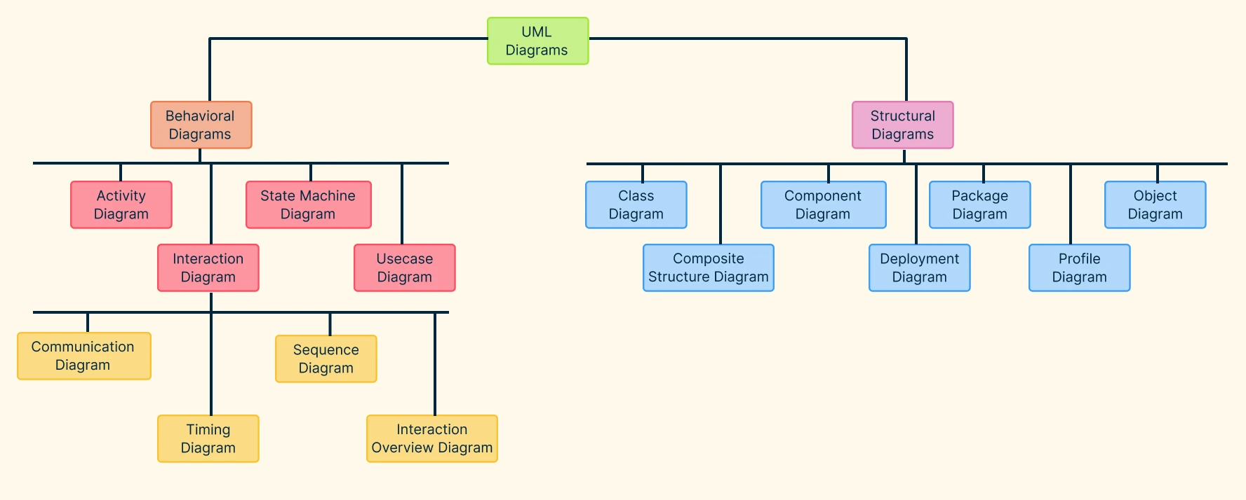
The Unified Modeling Language (UML) provides a standard vocabulary for visualizing, specifying, constructing, and documenting the artifacts of a software system. Its diagrams are broadly divided into two families: Structural and Behavioral.
- Structural Diagrams show the static structure of the system and its parts. They depict the things that are in the system, like classes, components, and their relationships. They are the system's anatomy.
- Behavioral Diagrams show the dynamic behavior of the system over time. They depict what the system does, like workflows, interactions between objects, and state changes. They are the system's physiology.
The following image provides a classic overview of this categorization.
To get a quick verbal overview of these categories, let's watch the introduction to a comprehensive course on UML.
UML Diagrams Full Course (Unified Modeling Language)
This clip from the "UML Diagrams Full Course" on the freeCodeCamp.org channel introduces UML and clearly defines the two primary categories of diagrams.
Please watch the first few minutes, from the beginning until the overview concludes. The narrator will list the seven types of structure diagrams and the seven types of behavior diagrams that constitute the UML standard.
As you heard, there are many diagram types, each with a specific purpose. You don't need to memorize them all right now. The key takeaway is the fundamental distinction: are you trying to show what the system is or what it does?
Frameworks for Viewing a System
To bring order to this variety, architects have developed models that define different views of a system. A view is a projection of a system from a particular perspective, intended for a particular audience. We'll look at two influential frameworks.
The 4+1 Architectural View Model
Proposed by Philippe Kruchten, the 4+1 model organizes the description of a software architecture using five concurrent views. Each view addresses a specific set of concerns.
4 + 1 Views in Modeling System Architecture with UML - Visual Paradigm Guides
This guide from Visual Paradigm provides a concise introduction to the 4+1 view model and, most importantly, maps each view directly to the UML diagrams used to represent it.
First, read the introductory sections that describe each of the five views: Logical, Process, Physical, Development, and Use Case (the "+1"). Then, carefully study the table under the heading The context of the “4 + 1” views model. This table explicitly connects the abstract views to concrete UML diagram types.
To summarize the relationship between the 4+1 views and the UML categories:
- Logical & Development Views are primarily described by Structural diagrams (Class, Component, Package). They address what the system is made of and how it's organized.
- Process View is described by Behavioral diagrams (Activity, State, Sequence). It addresses the system's runtime behavior and concurrency.
- Physical View is described by a Structural diagram (Deployment). It addresses how software is deployed on hardware.
- Use Case View (the "+1") is described by a Behavioral diagram (Use Case). It captures the system's functional requirements from an external user's perspective, driving the other four views.
The C4 Model for Software Architecture
While the 4+1 model is a comprehensive, formal framework, the C4 model offers a more modern, developer-focused approach to visualizing software architecture. C4 stands for Context, Containers, Components, and Code—a series of four hierarchical diagrams that allow you to zoom into a system at different levels of detail.
Given your role as a lead developer, this model provides a very practical vocabulary for architectural discussions.
Diagram Notation Selection — C4 vs PlantUML vs Mermaid
This section explains the four levels of the C4 model and their intended audiences.
Please read the section C4 Model — Strengths and Weaknesses. Focus on understanding the purpose and audience for each of the four levels.
The power of the C4 model lies in its prescriptive nature. It forces you to maintain a single level of abstraction in each diagram, which prevents the confusion we discussed at the start of the lesson.
Putting It Together: A Decision Process
Now, let's connect these frameworks to the learning outcome: selecting the right diagram for a specific question. Here is a practical thought process:
- What question am I trying to answer? (e.g., "How does this feature work?" "What services does our app depend on?")
- Who is my audience? (e.g., A new developer? A DevOps engineer? A business analyst?)
- What architectural view does this correspond to? (e.g., Is this about process, logical structure, or deployment?)
- Based on the view, what diagram type is most appropriate?
Let's apply this to a few scenarios:
| Question To Answer | Audience | View(s) | Recommended Diagram(s) |
|---|---|---|---|
| "What are the key objects in our system and their static relationships?" | Developers | Logical (Structural) | Class Diagram or Entity-Relationship Diagram (ERD) |
| "How does a user's API request flow through our services to return a result?" | Developers, API users | Process (Behavioral/Interaction) | Sequence Diagram |
| "What is the step-by-step business workflow for approving a purchase order?" | Business Analysts | Process (Behavioral) / Use Case | Activity Diagram or Flowchart |
| "How will our application, database, and message queue be deployed across our AWS infrastructure?" | DevOps, Architects | Physical (Structural) / C4 Container | Deployment Diagram |
| "What are the major systems our application interacts with, for a high-level overview for new stakeholders?" | All Stakeholders | Use Case / C4 System Context (Architectural) | Use Case Diagram or a C4 Context Diagram |
To get a better feel for some of these specific diagram types, the video from ArjanCodes provides quick, practical explanations of four of the most common ones you'll encounter.
Mermaid JS: Finally There's A Great UML & Diagram Drawing Tool
This video introduces Mermaid.js by demonstrating four key diagram types. While we'll cover the Mermaid syntax later, the conceptual explanations are excellent for understanding the purpose of each diagram.
Feel free to watch the sections that interest you most, but I recommend paying attention to the purpose described for each: Flowcharts for modeling user and application flows: Flowchart Sequence Diagrams for visualizing interactions between multiple participants: Sequence Diagram Class Diagrams for modeling static structure and relationships: Class Diagram Entity-Relationship Diagrams for modeling domain concepts and data: ER Diagram
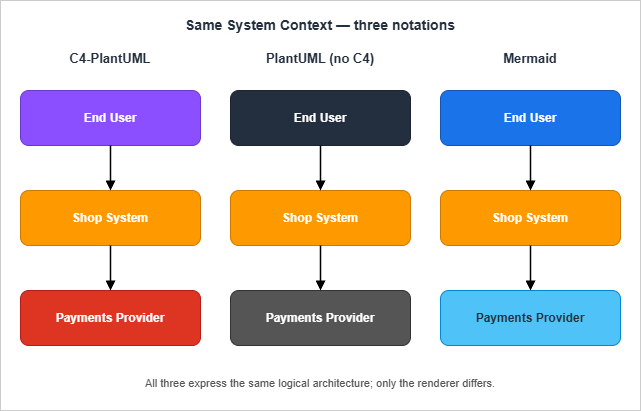
Finally, it's important to separate the conceptual diagram from the tool used to render it. Mermaid, which we will focus on in this course, is one of several "diagrams as code" notations. The same architectural idea can be rendered using different tools, each with its own visual style.
Conclusion
In this lesson, we've surveyed the landscape of software diagrams without getting lost in the details of any single one. We established that the primary goal of any diagram is to answer a specific question for a specific audience.
Here are the key takeaways:
- Diagrams answer questions. Start with the question, not the tool.
- UML diagrams fall into two main families: Structural (what the system is) and Behavioral (what the system does).
- Architectural frameworks like 4+1 and C4 provide structured ways to think about the different views needed to describe a system comprehensively.
- Selecting the right diagram involves matching the question and audience to the appropriate view (Logical, Process, Physical, Architectural) and then choosing the corresponding diagram type (Class, Sequence, Deployment, etc.).
Now that you have a mental map of the different kinds of diagrams and their purposes, we are ready to get our hands dirty. In the next lesson, you will learn how to use the Mermaid syntax and the Mermaid Live Editor to render, validate, and troubleshoot your very first diagram.