Recommended resources
The freely available resources this lesson will direct you to.
Hello! Let's dive into the next topic.
In our previous lessons, we explored how resistors combine in series and parallel. We established two fundamental rules: in a series circuit, the current is the same through all components, while in a parallel circuit, the voltage is the same across all components.
Today, we'll leverage our understanding of series circuits to develop a powerful shortcut called the Voltage Divider Rule. This lesson will not only give you a new tool for analysis but will also deepen your physical intuition for how voltage behaves. Your goal is to apply the voltage divider rule to series circuits and explain intuitively why voltage splits proportionally to resistance.
1. The Core Intuition: Why Voltage Divides
Before we touch any formulas, let's build the physical intuition. You already know two key facts about a series circuit:
- The current () is constant everywhere in the loop.
- The voltage drop across a resistor is given by Ohm's Law, .
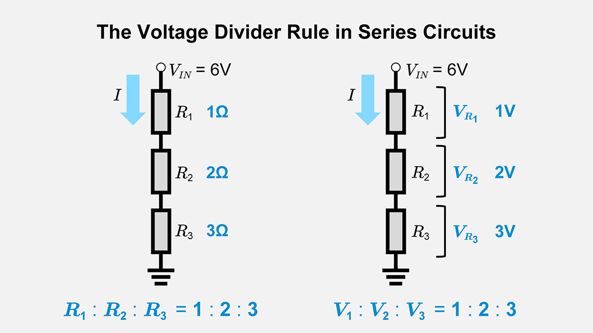
Putting these together, if the current is the same for every resistor in a series chain, then the voltage drop across any specific resistor must be directly proportional to its resistance . A larger resistance requires a larger "push" (voltage) to maintain the same rate of flow (current).
But how does the circuit "know" to do this? How are these specific voltages established? The answer lies in a fascinating, near-instantaneous process of charge redistribution that happens when a circuit is first powered on.
The following video provides a superb intuitive explanation of this process. It looks at the chaotic "transient state" to reveal how the stable, steady-state voltages we measure are created.
Why resistors in series have different voltage (but same current)?
This video from FloatHeadPhysics explains the physics behind why voltage divides across series resistors. It answers the question by examining what happens in the first milliseconds after a switch is closed.
Watch the entire video (up to 14:15). Focus on how the initial, non-uniform current causes a 'traffic jam' of charges to accumulate at the ends of the resistors. These accumulated charges create electric fields that, in turn, establish the precise voltage drops needed to make the current uniform throughout the circuit. Notice how a larger resistor leads to a larger charge buildup and thus a larger voltage drop.
The key takeaway is that the voltage drops aren't magically "assigned" by the battery. They are a self-correcting consequence of charge behavior. A higher resistance creates a bigger initial disruption to current flow, leading to a larger accumulation of surface charges, which in turn creates the larger voltage drop needed to force the steady-state current through. This directly results in the voltage being divided in proportion to the resistance.
2. Deriving the Voltage Divider Formula
Now that you have the physical intuition, let's formalize it into a convenient equation. We can derive this rule using the concepts you already know: series equivalent resistance and Ohm's Law.
Voltage divider (article) | Circuit analysis - Khan Academy
The article 'Voltage divider' from Khan Academy provides a clear, step-by-step derivation of the formula. We'll use this to build the mathematical tool from our intuitive understanding.
Read the beginning of the article, from the top down to the end of the section that introduces the voltage divider equation (before the 'Example' section). Follow the logic as it combines the formula for total series resistance with Ohm's Law to find an expression for the output voltage, V_out.
As the article shows, for a simple series circuit with two resistors, and , and an input voltage , the voltage across () is:
This is the voltage divider formula.
Notice how the formula perfectly matches our intuition:
- The term is the fraction of the total resistance that represents.
- The output voltage is simply this same fraction of the total input voltage.
This generalizes to any number of resistors. The voltage across any resistor in a series chain is:
where is the sum of all resistances in the series chain. This allows you to find the voltage across any series resistor without ever calculating the current!
3. Application and a Practical Example
Let's see how this rule is used in a practical context. Voltage dividers are one of the most common circuit patterns, often used to provide a specific, lower voltage from a higher voltage source.
Voltage Divider Explained | Animated Deep Dive
The video 'Voltage Divider Explained' by Voltverse walks through a practical application and reinforces the concept using an energy analogy.
Watch the first 2 minutes and 51 seconds. Pay attention to how the energy carried by charges (Joules per Coulomb) is 'spent' to get through each resistor, resulting in a voltage drop. This directly aligns with the idea of energy conservation (KVL) that we've discussed.
The video's example—using a 12V battery to power a 3V LED—is a classic use case. By choosing the right ratio of resistors, you can tap off a precise voltage.
Let's try one of the practice problems from the Khan Academy article you read earlier.
Practice Problem:
Consider a circuit where , , and . Find , the voltage across .
Solution:
Using the voltage divider formula:
The voltage across is 1V. By KVL, the remaining 5V must be across . You can verify this: .
4. A Crucial Reality Check: The Effect of a Load
Our derivation and formula rely on a key assumption: that no current flows out of the divider's central tap point. This is known as an unloaded voltage divider. In the real world, you build a voltage divider to power something—a load. This load has its own resistance and will draw current.
How does this affect our calculation? Let's investigate.
Voltage divider (article) | Circuit analysis - Khan Academy
Connecting a load fundamentally changes the circuit. This advanced section in the Khan Academy article is excellent for developing your critical thinking about ideal models versus real-world behavior.
Read the section titled 'Review the assumption (advanced)'. This part analyzes what happens when a 'load' resistor is connected in parallel with R2. Notice how this parallel combination lowers the resistance of the bottom part of the divider, which in turn lowers the output voltage from the ideal, calculated value.
When you connect a load resistor across , the bottom half of the divider is no longer just . It's in parallel with . As we learned in the last lesson, the equivalent resistance of a parallel combination is always less than the smallest individual resistance.
So, the new equivalent resistance of the bottom leg, , will be less than . When you plug this smaller value back into the voltage divider formula, you get a lower output voltage than you originally intended.
The Rule of Thumb: For a voltage divider to be "stiff" (i.e., its voltage doesn't change much when loaded), the current drawn by the load should be small compared to the current flowing through the divider itself. This is achieved when the load resistance is much larger (at least 10 times larger) than the divider resistor it's connected across ().
Conclusion
Today, we've added the voltage divider rule to your analytical toolkit. More importantly, we've explored the deep physical reasoning that underpins it.
Key Takeaways:
- Intuitive Reason: In a series circuit, current is constant. Per Ohm's Law (), the voltage drop across each resistor must be directly proportional to its resistance. This proportionality is physically established by the self-organization of surface charges on the wires and resistors.
- The Formula: The voltage across a specific resistor in a series circuit is a fraction of the total voltage, determined by the ratio of to the total resistance: .
- Practical Limitation: The ideal voltage divider formula assumes no load. When a load is connected, it draws current and reduces the output voltage. The effect is minimal if the load resistance is significantly larger than the divider's resistance.
Preview of the Next Lesson:
We've just seen how voltage divides in series circuits. The natural next question is: how does current divide in parallel circuits? In the next lesson, we will explore the dual of today's topic: the Current Divider Rule, which will give us a powerful shortcut for analyzing parallel branches.