Recommended resources
The freely available resources this lesson will direct you to.
Hello! Last lesson, you built a two-resistor divider by giving each schematic node a place on the breadboard. This lesson is about checking the build rather than trusting its appearance. You’ll use a multimeter to verify connections with the power off, then check supply polarity and node voltages with the power on.
If you have the battery divider from last lesson and a digital multimeter, allow about 40 minutes, including the short readings, videos, and measurements. The same checks will later help you find wiring and bias faults in a guitar pedal.
First, choose the kind of measurement
A multimeter does not test everything in the same way. Continuity and resistance tests use the meter’s own small test signal, so the circuit must be unpowered. DC voltage tests measure an existing potential difference, so the circuit or battery must be connected.
For all three tests in this lesson, plug the black lead into COM and the red lead into the jack marked V and/or Ω. Do not put the red lead in an A, mA, or 10A current jack. In particular, never place a meter set to current measurement across a battery or across the supply rails: that can create a short circuit.
The dial markings vary by meter. Look for Ω for resistance, a sound-wave or buzzer symbol for continuity, and V with a solid line over a dashed line for DC voltage. V~ denotes AC voltage and is not the setting for the battery checks here. If your meter has manual ranges, select a range above the value you expect—for example, a 20 V DC range for a 9 V battery.
Watch the setup and demonstrations in Multimeter: Guitar Diagnostics from Science of Loud. The examples use guitar equipment, but the lead placement and basic measurements apply directly to your breadboard.
Multimeter: Guitar Diagnostics
Watch how the meter is connected, how its continuity indication is checked, and how DC battery voltage is selected and measured.
Start with lead connections: note the COM and voltage/resistance jacks. Then watch continuity setup, particularly the check made by touching the probes together. Finally, skip to battery voltage and distinguish the DC setting from the resistance setting.
For a written reference, read the selected parts of Fluke’s How to Use a Multimeter: A Comprehensive Guide. Its safety section covers equipment beyond our battery circuit; do not treat a meter’s voltage rating as permission to probe mains-powered equipment. This lesson stays with a disconnected or battery-powered low-voltage build.
How to Use a Multimeter: A Comprehensive Guide
Fluke introduces the meter controls and the four checks that matter here: resistance, continuity, DC voltage, and safe separation of powered from unpowered tests.
In “Get to Know the Parts of the Multimeter,” read from “Familiarizing yourself with your multimeter is an essential first step” through the bullet ending “device or circuit you're testing.” Use the meter parts to locate the dial and input jacks. Under “How to Use Your Multimeter,” read “How to Measure Resistance” and “How to Test for Continuity,” beginning “Set the rotary switch to the resistance” and ending “the circuit is open or broken.” Follow both procedures, then find “How to Measure DC Voltage”: read from “Set the rotary switch to the appropriate DC voltage setting” through “Read the DC voltage on the multimeter's display.” See DC voltage. Finally, in “Safety Tips,” read the bullets beginning “Never attempt to measure voltage greater than 600V” and ending “Always turn off circuit power and discharge all high-voltage capacitors before testing resistance, continuity, diodes, or capacitance.” Focus on power-off testing; the battery divider has no large capacitor, but future circuits may retain charge after disconnection.
With power off: find connections, not just beeps
Disconnect the battery from the breadboard before using continuity or resistance mode. Keep its loose leads from touching each other. Set the meter to continuity and touch the probe tips together first. A beep or a reading close to confirms that the leads and selected mode are working. With the probes apart, many meters show “OL,” “1,” or another over-range indication; check what your meter displays.
Continuity is especially useful for checking the breadboard’s hidden connections. On the divider from last lesson, place one probe in an unused hole on the midpoint row M and the other in a different hole in that same five-hole group. You should find a low-resistance connection. Repeat from the positive rail to R1’s supply-side row, and from the ground rail to R2’s ground-side row. If a connection you expected is missing, check for a jumper in the wrong row or a split power rail.
A beep means the resistance between the probe points is below that meter’s beep threshold; it does not prove the points are connected by a direct wire. A missing beep does not prove that no path exists. For example, the unpowered divider has a path from its positive node to ground through two resistors, but that path may not make the meter beep. Use continuity chiefly to confirm intended near-zero-resistance connections. If positive and ground do beep in this simple divider, stop and look for a possible short before connecting the battery.
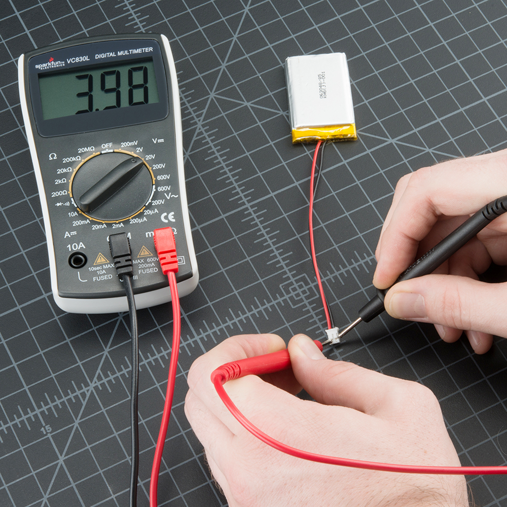
The image shows the same principle on a separate component: the probes touch opposite ends of a fuse to check for a conducting path. Our breadboard check should likewise be done without power.

With power off: measure resistance
Switch to Ω mode while the battery remains disconnected. To check a resistor’s value most reliably, measure it before installation, or lift one of its leads out of the breadboard. Place one probe on each end. Lead orientation does not matter for an ordinary resistor. A part should read approximately , within its tolerance and your meter’s accuracy.
You can also measure across the divider’s positive and ground nodes while its battery is disconnected. With two resistors in series and no other connected parts, expect approximately . On a manual-ranging meter, a 20 kΩ range may be too small for an actual value slightly above ; choose the next range up if it displays over-range.
Resistance measured in an assembled circuit needs interpretation. The meter responds to every available path between its probes, not necessarily just the component you meant to inspect. As pedal circuits become more complex, parallel components can make an in-circuit resistor reading lower than its marked value. An “OL” reading may mean an open path or an insufficiently high range; a near-zero reading may mean a short or simply that you are probing two points on the same node.
Keep resistance and continuity mode away from a powered board. Disconnecting the source matters even when you only intend to touch one resistor: the probes may contact a neighboring hole.
With power on: establish a reference and check polarity
Set the meter to DC voltage and confirm again that the red lead is in the V/Ω jack, not a current jack. A voltage reading compares two points. The display reports the voltage at the red probe relative to the black probe:
Start with the battery separate from the breadboard. Touch black to battery negative and red to battery positive. A healthy battery might read around , but its actual voltage is the useful number. If the display reads approximately , the probes are reversed relative to those battery terminals. Disconnect the probes before wiring the battery to the board.
Now visually check that battery positive will go to the divider’s positive rail and battery negative to its ground rail. Connect the battery. If possible, secure or clip the black probe to the known ground rail; make this connection carefully so the clip cannot touch an adjacent node. Touch the red probe to the positive rail. The reading should be positive and close to the battery voltage you just measured.
Watch how Fault Diagnosing: Measuring Voltages from DIY Guitar Pedals uses a fixed ground connection, then verifies that voltage actually reaches the circuit. On your unenclosed breadboard, use battery negative or its confirmed ground rail as ground; do not assume that some nearby metal object is grounded.
Fault Diagnosing: Measuring Voltages (DIY Guitar Pedals)
Watch the presenter secure the negative probe and test the positive supply point. This keeps the voltage reference steady while the other probe moves.
Watch ground and supply. Notice why a secure ground contact helps avoid misleading readings, and how the positive-rail measurement confirms that power reaches the circuit.
Use the insulated probe grips and steady the board. A probe tip that slips across two adjacent nodes can short them. A 9 V battery is low voltage, but a short can still heat the battery, wires, or components. If a lead or part becomes hot, disconnect the battery.
Measure the divider’s three node voltages
Leave the black probe on the divider’s ground node. Touch the red probe to each node separately, recording what the meter actually shows. If your battery measured , for example, two equal resistors predict a midpoint near , not necessarily exactly .
| Red-probe node; black remains on ground | Expected DC reading |
|---|---|
| Ground | Approximately |
| Positive supply | Approximately the battery voltage, positive |
| Midpoint M | Approximately half the measured supply voltage |
This is why a reference point matters. M is not ground merely because it is the divider’s “middle” connection. A reading at M means . With equal resistors and no load attached, the prediction is
Measure at an unused hole in M’s five-hole group rather than trying to balance a tip between resistor leads. Your meter may show slight fluctuations or a value modestly different from the prediction because the battery, resistors, and contacts are not ideal.
If M reads close to ground while the positive rail reads normally, R1 might be disconnected or M might be unintentionally connected to ground. If M reads close to the positive rail, R2 might be disconnected or M might be joined to the positive rail. A voltage reading suggests where to inspect; it does not identify the fault by itself. Disconnect the battery before returning to continuity or resistance mode to test a suspected connection.
A DC node measurement checks the circuit’s resting condition—the operating point discussed earlier—not the changing guitar waveform. Later, a midpoint near half the supply can serve as a bias reference in a single-supply audio circuit.
Why polarity and supply checks matter in pedals
When you move beyond a battery on a breadboard, do not infer a supply’s polarity from its voltage rating. Many guitar pedals use center-negative DC connectors, but the circuit and supply must be checked against their own specifications. A connector of the wrong polarity can damage an unprotected circuit. For now, the safest supply for this divider is the known battery; do not open or probe mains-powered equipment or an amplifier.
Read the selected passages in Amplified Parts’ Pedal Troubleshooting Guide to see how these measurements scale up. The useful pattern is to verify the specified supply and polarity, then measure where power enters the board and at points meant to share its supply node.
Pedal Troubleshooting Guide | Amplified Parts
Amplified Parts connects supply polarity and board-entry voltage measurements to common pedal faults.
Under “No signal when effect is engaged, clean signal in bypass mode (or no signal in buffered bypass mode),” find “Incorrect Power Supply.” Read from “Make sure that a correct power supply is used” through “unless noted otherwise,” including the center-polarity symbol figure; use supply specifications to check why voltage alone is insufficient. Immediately below the figure, read from “Using a center-positive supply with a pedal that calls for a center-negative supply will not work” through “if the circuit does not have polarity protection”; see wrong polarity. Then find “Board/Components Do Not Receive Power.” Begin at “With a multimeter, measure the voltage at the point where power enters the board” and continue past Figure 4 to the paragraph ending “there are no obvious shorts.” Follow board-entry checks, noting that a downstream supply point can differ from the source when components intervene.
What to carry forward
Keep the two meter routines distinct: disconnect power for continuity and resistance; use DC voltage mode to measure a powered circuit. Check the lead jacks and dial before probing, establish a known ground for node voltages, and compare each reading with the circuit’s predicted value. On your divider, that means near-zero-resistance connections within each intended node, a positive supply reading, and an unloaded midpoint near half the measured supply.
This completes the first module’s path from schematic to breadboard to measurement. Next, you’ll apply these circuit habits to guitar signals, beginning with how a pedal’s input can load a passive pickup.