Recommended resources
The freely available resources this lesson will direct you to.
- VPNs, Proxies and Secure Tunnels Explained (Deepdive)www.youtube.com
- The Power of Zero-Trust Architecture: Building a Secure Internal Network with Nebulawww.youtube.com
- Zero Trust Architecture - NIST Technical Series Publicationsnvlpubs.nist.gov
- Network Engineer's Guide - Private Accesstrusted.jamf.com
Hello! Welcome to the first lesson of our module on Architecting Zero Trust Network Access (ZTNA).
In our previous module, we concluded by designing a robust, cross-region federation model for a global identity platform. We established how to authenticate users securely and reliably, no matter where they are, while respecting complex data residency laws. This strong, verifiable identity is the absolute bedrock upon which the entire Zero Trust security model is built.
Today, we take that foundational concept of identity and apply it to network access itself. This lesson directly addresses the learning outcome: Design the end-to-end connection flow for a ZTNA service, contrasting the data and control planes with a traditional VPN architecture. We will move past the old "castle-and-moat" security model and architect the "never trust, always verify" approach from first principles.
1. The Paradigm Shift: From Trusted Networks to Zero Trust
For decades, enterprise security was built around the idea of a trusted internal network protected by a strong perimeter (firewalls, VPN gateways, etc.). Once a user connected via a VPN, they were effectively "inside the castle" and granted broad access. This model is no longer sufficient in a world of cloud applications, remote work, and sophisticated attackers who, once inside, can move laterally with ease.
Zero Trust dismantles this idea of a trusted network. It assumes that threats exist both outside and inside the network. Therefore, trust is never granted implicitly; it must be continuously verified for every single access request.
To understand this shift, let's explore the limitations of the traditional model and how Zero Trust, implemented via an overlay network, changes the game.
The Power of Zero-Trust Architecture: Building a Secure Internal Network with Nebula
This video provides an excellent introduction to the core philosophy of Zero Trust by demonstrating a practical implementation with Nebula. It clearly contrasts the old perimeter-based model with the new node-based, identity-driven approach.
Please watch the segment from 05:05 to 10:34. Focus on how the video illustrates the shortcomings of the traditional firewall/VPN model and how Zero Trust fundamentally changes the architecture by distributing the 'firewall' to each node and basing access decisions on cryptographic identity (certificates) rather than network location.
This conceptual shift is formally defined by a set of core principles or tenets. Understanding these is crucial to architecting any Zero Trust system correctly.
NIST SP 800-207: Zero Trust Architecture
The definitive guide for Zero Trust Architecture is the NIST Special Publication 800-207. We will use it to ground our understanding in the official, foundational tenets.
Please read the following sections of this PDF: Section 2: Zero Trust Basics (page 4): Focus on the operative definition of Zero Trust (ZT) and Zero Trust Architecture (ZTA). Section 2.1: Tenets of Zero Trust (pages 6-7): This is the most important part. Internalize these seven tenets as they are the guiding principles for our entire design. Section 2.2: A Zero Trust View of a Network (page 8): Understand the core assumptions about the network in a ZT model (e.g., 'The entire enterprise private network is not considered an implicit trust zone').
The key takeaway from the NIST document is Tenet #3: Access to individual enterprise resources is granted on a per-session basis. This is the antithesis of the traditional VPN model, where access is granted to the entire network for the duration of a connection.
2. Contrasting Architectures: VPN vs. ZTNA
To design the ZTNA flow, we must first understand the mechanics of what it replaces.
The Traditional VPN Architecture
A Virtual Private Network (VPN) creates an encrypted tunnel between a user's device and the corporate network. From a system design perspective, its primary function is to extend the private corporate network to the remote user.
VPNs, Proxies and Secure Tunnels Explained (Deepdive)
This LiveOverflow video gives a fantastic deep-dive, from first principles, into how proxies and tunnels work. This will give you a solid mental model of the underlying network mechanics of a VPN.
Watch the sections from 06:27 to 12:20. Pay close attention to: The explanation of how a VPN encapsulates entire IP packets, contrasting it with a simple proxy. The concept of a virtual network interface (TUN/TAP), which is the OS-level mechanism that allows a program (the VPN client) to intercept and manipulate network packets.
The typical VPN connection flow is as follows:
- Authentication & Tunneling: The user authenticates (often once) to a VPN concentrator. A virtual network interface (e.g.,
tun0) is created on the user's device, and a secure tunnel (like IPsec or OpenVPN) is established to the concentrator. - IP & Route Assignment: The device is assigned an IP address from the corporate network's private range. The VPN server then "pushes" routes to the client, telling its operating system to send all traffic destined for corporate subnets (e.g.,
10.0.0.0/8) through thetun0interface. - Network-Level Access: The user's device is now logically on the corporate network. It can attempt to connect to any IP address within the routed subnets, subject only to downstream network firewalls. This grants broad, network-level access.

The ZTNA Architecture: Separating Control and Data
ZTNA fundamentally re-architects this flow by separating the decision to grant access (the control plane) from the user's actual traffic (the data plane).
Let's return to the NIST document to formally define these components.
NIST SP 800-207: Zero Trust Architecture
The NIST ZTA document provides the abstract model for how a ZTNA system is logically structured.
Please read these two key sections: Section 3: Logical Components of Zero Trust Architecture (pages 9-10): Focus on the definitions of the Policy Engine (PE), Policy Administrator (PA), and Policy Enforcement Point (PEP), and look at Figure 2. This is the core logical model. Section 3.4: Network/Environment Components (page 21): Read the introduction and point #5, which explicitly define the separation of the control plane and data plane. This concept is central to our learning outcome.
In short:
- Control Plane: The communication channel used by the ZTNA components (Agent, Policy Engine, etc.) to decide if a user should be allowed to connect to a resource. It handles authentication, device posture checks, and policy evaluation.
- Data Plane: The path that the user's application traffic follows to the resource after the control plane has approved the request and configured the path.
This separation allows for a "default deny" posture. No data path exists until the control plane explicitly creates one on a per-session, per-application basis.
3. Designing the End-to-End ZTNA Connection Flow
Now, let's put it all together and design the step-by-step connection flow. We'll use a "connection brokering" model, which is a common and powerful implementation of the ZTA principles.
Network Engineer's Guide to Private Access
This guide from Jamf provides an exceptionally detailed, engineer-focused walkthrough of a modern ZTNA connection flow. It perfectly illustrates the interplay between the control plane and data plane.
This is our primary resource for this section. Please read it carefully: Start with the 'Traditional VPN' subsection to see their summary. Then, dive deep into the section titled 'SDP: Connection Brokering'. Read this entire section, including the numbered step-by-step flow. This is the core of the lesson. Finally, read 'Server/Infrastructure-to-Client Connections' to understand a key security benefit of this architecture.
Let's distill that detailed flow into its essential architectural steps. Imagine a user wants to access an internal service wiki.corp.internal at 10.50.1.100.
The Connection Flow:
-
Initiation: The user types
https://wiki.corp.internalinto their browser. The OS needs to resolve this hostname to an IP address. -
DNS Interception (Control Plane starts):
- The ZTNA agent running on the device has configured the OS to use a local DNS resolver (e.g., pointing to an address like
127.0.0.53or a special IPv6 address likefddd:dddd::). - The agent intercepts the DNS query for
wiki.corp.internal.
- The ZTNA agent running on the device has configured the OS to use a local DNS resolver (e.g., pointing to an address like
-
Policy Evaluation (Control Plane):
- The agent sends the access request to the ZTNA control plane (the Policy Engine/Administrator). This request includes the user's identity (verified via mechanisms from our last module), device posture information, and the requested resource (
wiki.corp.internal). - The Policy Engine evaluates this against pre-defined access policies. Does this user, on this compliant device, have permission to access the wiki?
- The agent sends the access request to the ZTNA control plane (the Policy Engine/Administrator). This request includes the user's identity (verified via mechanisms from our last module), device posture information, and the requested resource (
-
Connection Brokering (Control Plane):
- If denied: The agent returns a standard
NXDOMAIN(domain not found) response to the OS. The connection fails. - If approved: The control plane performs its magic. It creates an ephemeral, one-time mapping in its cloud fabric: a unique, non-routable IP address is mapped to the real internal IP.
- Example mapping:
fd53:1c5a::1234:5678->10.50.1.100:443
- Example mapping:
- This ephemeral IPv6 address is returned to the agent.
- If denied: The agent returns a standard
-
Synthetic DNS Response (Control & Data Plane Bridge):
- The agent provides the ephemeral IPv6 address (
fd53:1c5a::1234:5678) as theAAAArecord in response to the original DNS query. - Crucially, the user's device never learns the real internal IP address (
10.50.1.100). The internal network topology remains completely hidden.
- The agent provides the ephemeral IPv6 address (
-
Tunnel Establishment (Data Plane):
- The user's browser now attempts to open a TCP connection to
fd53:1c5a::1234:5678. - The ZTNA agent has already configured the OS routing table so that all traffic destined for the
fd53:1c5a::/32prefix is routed through its virtual network interface. - The agent encapsulates this packet into a secure tunnel (e.g., WireGuard) and sends it to the nearest ZTNA service edge point.
- The user's browser now attempts to open a TCP connection to
-
Cloud-Side Routing (Data Plane):
- The ZTNA service edge receives the tunneled packet. It decrypts it and sees the destination is
fd53:1c5a::1234:5678. - It looks up this ephemeral IP in its flow mapping table and finds the real destination:
10.50.1.100. - It performs a NAT64 (Network Address Translation from IPv6 to IPv4) and forwards the packet to the internal
wiki.corp.internalserver via a secure connector.
- The ZTNA service edge receives the tunneled packet. It decrypts it and sees the destination is
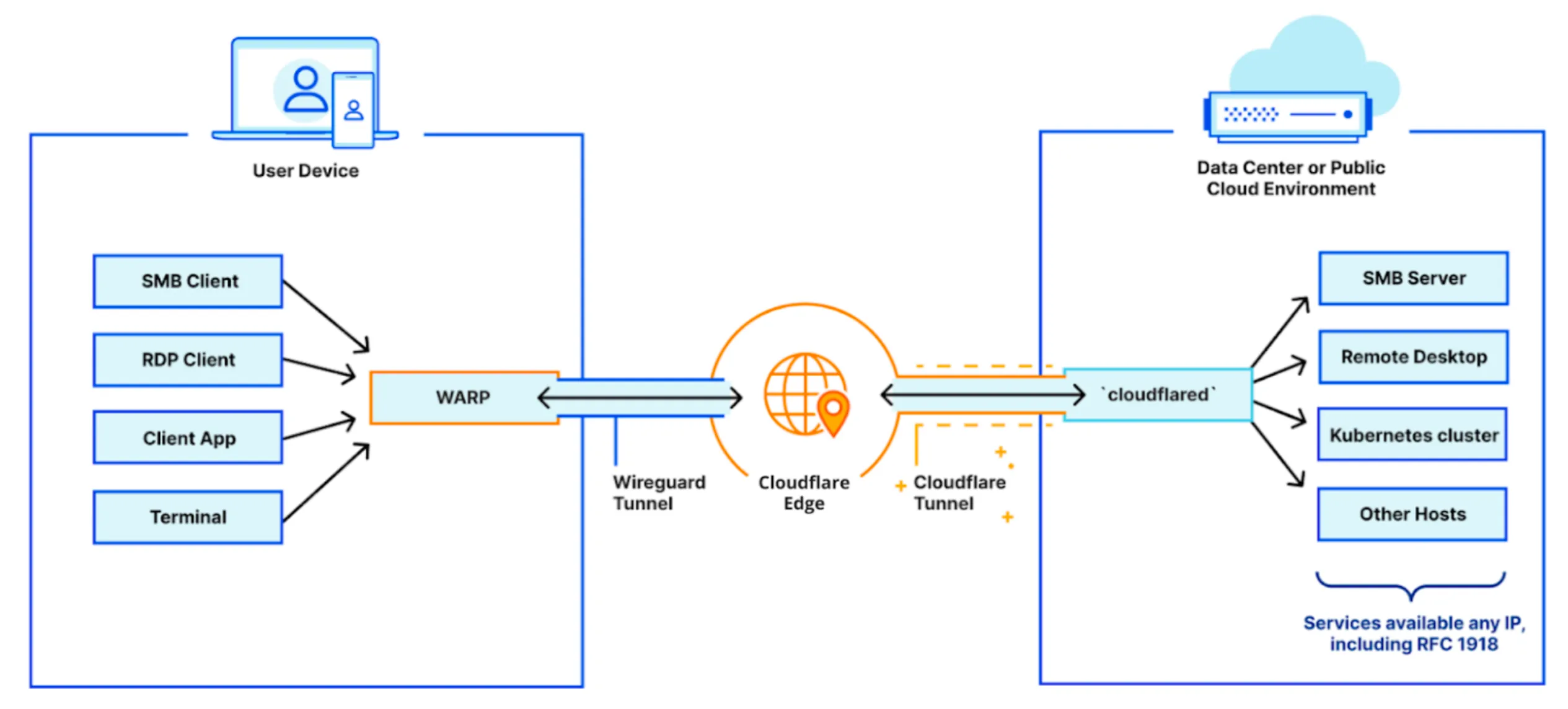
This flow elegantly demonstrates the separation: the control plane decides access and "brokers" a connection by creating a temporary mapping, and the data plane uses that mapping to shuttle packets without ever exposing the underlying network structure.
Conclusion
In this lesson, we have designed the end-to-end connection flow for a ZTNA service, contrasting it sharply with traditional VPNs. We have seen how the abstract principles of Zero Trust translate into a concrete, identity-driven architecture.
Key Takeaways:
- VPNs grant network access, ZTNA grants application access. A VPN puts you on the network; ZTNA creates a secure, brokered path to a specific application.
- The Control Plane and Data Plane are separate in ZTNA. Access is first requested and authorized on the control plane before a data path is ever established. In a VPN, these are largely intertwined.
- ZTNA hides network topology. By using DNS interception and connection brokering, ZTNA ensures that the client device never learns the internal IP addresses of resources, dramatically reducing the attack surface.
- ZTNA is "Default Deny". No connection is possible until explicitly permitted by a policy evaluation on the control plane. This is the opposite of the VPN model, which provides broad "Default Allow" access once connected.
Preview of the Next Lesson:
We've seen the Policy Engine act as the "brain" of the ZTNA service, making the critical approve/deny decision. But how does it make that decision? In our next lesson, we will dive inside this component and design the ZTNA policy engine, showing how it integrates identity and device signals into a dynamic trust score for access decisions. We will architect the system that turns Zero Trust principles into real-time, enforceable logic.