Recommended resources
The freely available resources this lesson will direct you to.
Introduction
Welcome to the next lesson in our exploration of large-scale AI systems. In our previous session, we confronted the statistical certainty of hardware and software failures in massive clusters and developed strategies for fault tolerance, such as distributed checkpointing. We established that to achieve a high Effective Training Time Ratio (ETTR), we must design systems that can recover gracefully from inevitable faults.
Many of those faults have physical origins—components failing under the immense stress of continuous, high-intensity operation. This brings us directly to today's topic, which addresses the learning outcome: Describe the key power and cooling considerations in designing and operating large-scale GPU deployments.
We will investigate the entire energy lifecycle within a datacenter: how vast amounts of electrical power are delivered to the chips and, just as importantly, how the resulting heat is removed. As you will see, power is rapidly becoming the single greatest constraint on the growth of AI compute, making its management a primary concern in modern system design. Understanding these physical constraints is fundamental to building reliable, efficient, and scalable AI infrastructure.
1. The Power and Density Explosion
The defining characteristic of AI datacenters is their incredible computational density. To minimize latency and maximize performance, designers pack as many GPUs as possible into a single rack. This trend, combined with the escalating power demands of each new GPU generation, has created an exponential increase in power consumption at every level.
To grasp the scale of this shift, let's compare traditional datacenters with the new breed of "AI supercomputers."
How AI Datacenters Eat the World
The video 'How AI Datacenters Eat the World' provides an excellent high-level overview of this paradigm shift. It vividly illustrates how AI datacenters are fundamentally different from their traditional counterparts.
Please watch from 04:06 to 11:36. Focus on the comparison of the four main components (C3P) and pay close attention to the dramatic growth in power consumption at both the chip level (Nvidia's GPU generations) and the rack level (from ~10 kW to over 100 kW).
As the video highlights, we are witnessing a profound escalation:
- Chip-level Power: A single GPU's Thermal Design Power (TDP) has grown from 250W (NVIDIA Volta) to 1000W (NVIDIA Blackwell), a 4x increase in just a few generations.
- Rack-level Power: A standard datacenter rack might consume 5-10 kW. An AI rack, like NVIDIA's GB200 NVL72, can consume over 130 kW—an order of magnitude more.
- Facility-level Power: Entire AI datacenter campuses are being built with power capacities of hundreds of megawatts, with plans for gigawatt-scale facilities, rivaling the power consumption of large cities.
This exponential demand is not just a brute-force approach; it's a direct consequence of architectural choices made to optimize for AI workloads, primarily by increasing compute density to reduce communication latency between processors.
2. Power Delivery: From the Grid to the GPU Core
Delivering over 100 kW of stable, clean power to a single rack and then converting it to the specific low voltages required by a processor is a major engineering challenge. The traditional power delivery architectures used in datacenters are not sufficient for this task.
This diagram shows the complete power delivery chain, from the high-voltage utility grid down to the GPU core.

The most critical innovations are happening inside the rack itself. As rack power density increases, delivering that power with traditional 12V systems becomes inefficient due to immense electrical currents and associated resistive losses (). This has driven a shift to higher-voltage DC distribution within the rack.
Reimagine AI data center power from grid to gate
The video 'Reimagine AI data center power from grid to gate' from Texas Instruments provides an excellent technical overview of the evolution of these power delivery architectures.
Please watch from 00:37 to 07:24. This segment explains the drivers for increased power demand and walks through the progression from traditional 12V systems to 50V bus architectures, and finally to the emerging 800V bus rack designs needed for megawatt-scale deployments.
Let's summarize the architectural evolution described in the video:
- Traditional 12V Architecture: Suitable for racks up to ~15 kW. Power Supply Units (PSUs) in each server convert AC to 12V DC.
- 48V/50V Bus Architecture: Used for racks up to ~100-200 kW. A central power shelf converts AC to ~48V DC, which is distributed along a bus bar. Intermediate Bus Converters (IBCs) on each server tray then step this down to 12V for the final conversion stages. Using a higher voltage reduces the current for the same amount of power (), thus lowering resistive losses.
- 800V Bus Rack Architecture: The next frontier for racks consuming several hundred kilowatts to over a megawatt. A high-voltage DC bus (e.g., 800V) runs down the rack, delivering power directly to the server trays. This requires high-voltage components on the server board but dramatically improves efficiency for delivering massive amounts of power by further minimizing current.
The move to higher voltages is a classic engineering trade-off, analogous to choices in data transmission: you can send more data by increasing bandwidth or using more complex modulation schemes. Here, to deliver more power, you either increase the current (which is lossy and requires thick, expensive copper) or increase the voltage (which is more efficient but introduces new safety and component design challenges).
3. Cooling: Managing the Inevitable Heat
Nearly all the electrical power consumed by a GPU is converted into heat. A rack drawing 100 kW of power is effectively a 100 kW space heater. Removing this concentrated heat is arguably the single greatest physical challenge in designing AI supercomputers.
The relationship between power and heat is fundamental. As the article "GPU Power Management: A Comprehensive Analysis" explains, the dynamic power consumed by a chip is approximately:
where is capacitance, is voltage, is the activity factor, and is frequency. This dissipated power manifests as heat that must be conducted away from the silicon. If heat is not removed faster than it is generated, the chip's temperature will rise until it triggers thermal throttling—a self-preservation mechanism where the GPU automatically reduces its frequency and voltage to lower power consumption and prevent physical damage.
Relying on thermal throttling is a sign of inadequate cooling. It means you are not achieving the full performance potential of your hardware. As rack power densities have surpassed the limits of conventional air cooling, the industry has pivoted to more advanced solutions.
[PDF] Considerations for Scaling GPU-Ready Data Centers - NVIDIA
The NVIDIA whitepaper 'Considerations for Scaling GPU-Ready Data Centers' provides a practical guide to designing for power and cooling. It clearly outlines the different cooling technologies and the power densities they can support.
Please read the section 'POWER AND COOLING' starting on page 6. Pay close attention to Table 2, which compares the rack power capacity of different cooling solutions, and Table 3, which provides concrete examples of server configurations with their power, airflow, and recommended cooling solutions.
The key cooling strategies outlined in the paper represent a clear progression:
- Traditional Air Cooling (up to ~8 kW/rack): Standard server room cooling, where cool air is pushed into the front of the rack and hot air is exhausted out the back.
- Hot/Cold Aisle Containment (up to ~15 kW/rack): An enhanced air-cooling method that physically separates the cool air supply from the hot air exhaust, preventing them from mixing and improving efficiency.
- Rear-Door Heat Exchangers (RDHX) (up to ~35 kW/rack): A hybrid approach where a liquid-cooled radiator is attached to the back of the rack. The hot air exhausted by the servers passes through this radiator, transferring its heat to the liquid before entering the room.
- Direct Liquid Cooling (60 kW+ /rack): The most effective method. Liquid is piped directly to cold plates mounted on the primary heat-generating components (like GPUs and CPUs). This captures heat at the source with maximum efficiency. Water can absorb about 4,000 times more heat per unit volume than air, making this essential for high-density AI racks.
This image shows a direct-to-chip liquid cooling implementation.
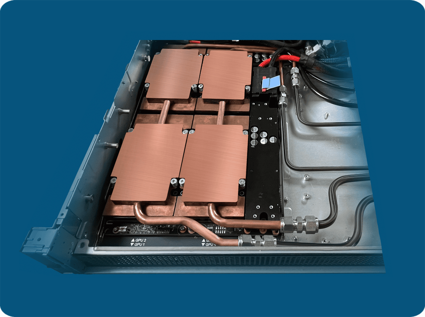
The transition from air to liquid cooling is a critical design inflection point, driven by the sheer density of AI workloads. It changes the entire layout of the datacenter, requiring extensive plumbing infrastructure, but it is the only viable path for staying competitive at the highest end of AI compute.
4. System-Level Management and Monitoring
Power and thermal management are not just about static hardware design; they involve a dynamic interplay between hardware, firmware, and software.
- Dynamic Voltage and Frequency Scaling (DVFS): As we've seen, this is the primary technique for actively managing power consumption. The GPU's power management unit continuously adjusts voltage and frequency based on the workload to optimize the trade-off between performance and power draw.
- Power Capping: In a datacenter with a fixed power budget from the utility provider, administrators cannot allow jobs to consume power without limit. Power capping is a critical feature, exposed through tools like the NVIDIA Management Library (NVML), that allows setting a maximum power limit for a GPU. This ensures the total facility power stays within its contracted envelope.
- Monitoring: System administrators use tools like NVIDIA's Data Center GPU Manager (DCGM) to monitor key metrics in real-time, including GPU temperature, power draw, and clock speeds. This data is essential for diagnosing issues, ensuring jobs are running efficiently, and preventing thermal throttling. As the NVIDIA whitepaper (LINK) notes, monitoring GPU temperatures is crucial to prevent throttling and maximize uptime.
These software controls, combined with the underlying power and cooling infrastructure, form a complete system for managing the physical realities of large-scale GPU deployments.
Conclusion
In this lesson, we have moved from the logical realm of algorithms and data pipelines to the physical world of watts and Celsius. We've seen that the design of modern AI supercomputers is increasingly dominated by the challenges of power and cooling.
Key Takeaways:
- Power as the Primary Bottleneck: The push for higher compute density has led to an order-of-magnitude increase in rack power, making power availability and delivery a primary constraint on datacenter scale.
- Evolving Power Architectures: To deliver hundreds of kilowatts per rack efficiently, datacenters are moving from traditional 12V systems to higher-voltage 48V and 800V DC bus architectures.
- The End of Air Cooling for HPC: The heat generated by dense GPU racks far exceeds the capacity of traditional air cooling. Liquid cooling, particularly direct-to-chip, is now a mandatory technology for high-end AI systems.
- A Co-Design Problem: Power, cooling, and compute are not independent variables. They must be co-designed. A decision to increase GPU density in a rack directly implies a more advanced and costly power delivery and cooling solution.
- Dynamic Management is Key: The system is managed dynamically through software and firmware, using techniques like DVFS and power capping to operate within strict thermal and power budgets while maximizing performance.
Preview of the Next Lesson:
Having now covered the system's reliability and its physical constraints, we will turn our attention to evaluating its performance. In the next lesson, we will begin Module 10 by learning how to "Define key performance metrics for distributed training, including throughput (e.g., TFLOPs/s), hardware utilization (MFU/HFU), and scaling efficiency." This will equip us with the vocabulary and analytical tools to measure how effectively our applications are using the powerful, complex, and power-hungry hardware we've just discussed.