Recommended resources
The freely available resources this lesson will direct you to.
Welcome to the fourth module of your course on UML and Mermaid. In the previous modules, you've explored diagrams that describe behavior and code structure, such as use-case, activity, and class diagrams. We are now shifting our focus from the application's logic to its data. While a class diagram models the structure of your code, an Entity-Relationship Diagram (ERD) models the structure of the information your application needs to store and manage.
This lesson will equip you with the fundamental concepts of data modeling. You will learn how to analyze a brief description of a system's requirements—what we call a "domain description"—and derive the core components of a data model: entities, their attributes, unique identifiers called primary keys, and the relationships that connect them. This conceptual groundwork is the essential first step before you can begin to diagram or build a database.
From Concept to Database: Levels of Data Modeling
When designing a system to handle data, it's helpful to think in layers of abstraction, moving from a high-level business concept to a concrete technical implementation. This is a familiar pattern in engineering and software development. In data modeling, we typically distinguish between three levels.
To understand these layers, please read the section on data model abstraction from the Wikipedia article on Entity-relationship models.
Start by finding the paragraph that begins, "An ER model is typically..." and read through the descriptions of the Conceptual, Logical, and Physical data models, ending before the paragraph that starts "The first stage...". As you read, focus on how each level adds more detail: Conceptual: The big picture, defining major entities. Logical: The detailed blueprint, defining all entities, attributes, and relationships, but without specifying the database technology. Physical: The implementation plan, specific to a database system like PostgreSQL or MySQL.
In this course, we will focus on creating logical data models. Your experience as a developer allows you to appreciate the value of separating the logical design from the physical implementation. A well-designed logical model serves as a clear, technology-agnostic blueprint that can be implemented in any relational database system.
The Building Blocks: Entities, Attributes, and Relationships
An ER model is built from a few simple, yet powerful, components. Understanding them is key to translating a domain description into a structured model.
- An Entity is a "thing" of significance that the system needs to track. It's typically a noun, like
Customer,Product, orOrder. - An Attribute is a property or characteristic of an entity. For a
Productentity, attributes might includename,price, andsku. - A Relationship describes how two or more entities are associated with each other. It's often a verb, such as a
Customerplaces anOrder.
A simple and effective method for identifying these components from a text description is to analyze its grammar.
The same Wikipedia article provides clear definitions for these components and a very useful heuristic for finding them.
Please read the "Components" section. Start from the definition of an entity. Then, read the paragraph defining a relationship. Finally, and most importantly, study the table under the heading "Guiding rules". This table provides a direct mapping from English grammar to ER structures and is an excellent practical tool.
The Primary Key: An Entity's Unique Identity
One attribute (or a combination of attributes) is special: the primary key. Its purpose is to provide a unique identifier for every single instance of an entity. For example, while two customers might share the same name, their customer_id must be unique. This is fundamental to how relational databases work; without a unique key, you cannot reliably retrieve or modify a specific record.
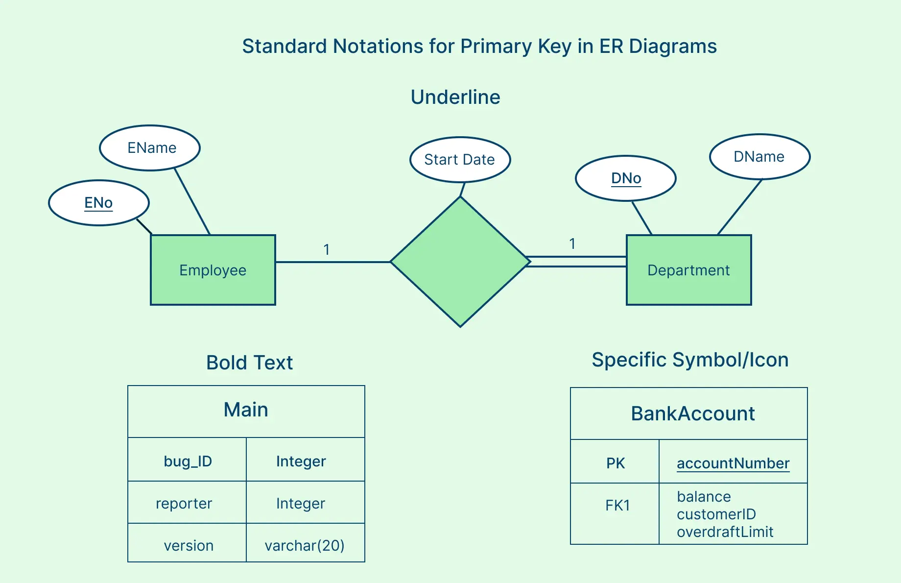
There are several common notations for indicating a primary key in a diagram, such as underlining the attribute, using bold text, or adding a "PK" marker.
A Systematic Approach to Data Modeling
Now let's put these concepts into practice with a structured process. We will see how to start with a set of requirements and systematically derive the entities, attributes, and relationships.
The following video provides an excellent walkthrough of this process, starting with a simple domain description for a pet ownership database. It demonstrates the "noun-finding" technique and the critical step of defining relationships.
This video from Decomplexify demonstrates the initial steps of creating an ERD from a set of requirements.
Watch the segment from "Getting Started", where the presenter identifies nouns from a requirements list to derive potential entities. Continue watching from "Defining Relationships". Pay close attention to how he asks questions to determine the nature of the connections between entities. This section introduces cardinality (e.g., one-to-many), which we will cover in depth in the next lesson.
From Business Rules to a Logical Model
Real-world projects often start with a list of business rules. These rules are constraints or statements about how the business operates, and they are a rich source of information for your data model.
Let's look at a more complex example. The next video walks through the creation of a logical ERD for a library circulation system based on a set of business rules. This demonstrates the full process of deriving entities, attributes, primary keys, and even foreign keys—which are primary keys from one entity used as an attribute in another to create a link.
Entity Relationship Diagram (ERD) Tutorial and EXAMPLE
This video from The Business Analysis Doctor provides a complete example of deriving an ERD from business rules.
Please watch the example walkthrough from "Library Case Study". The presenter does an excellent job of: Starting with business rules. Using the noun technique to identify entities (Book, Borrower, etc.). Defining attributes for each entity. Assigning a Primary Key (PK) to each entity. Using Foreign Keys (FK) to establish relationships.
The result of this process is a complete logical ERD, which might look something like this:
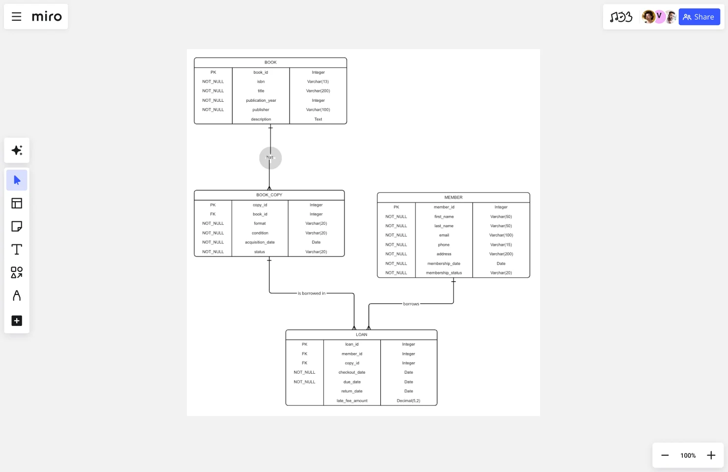
This diagram is the blueprint we'll learn to create using Mermaid in our next lesson.
Practice Exercise
Now it's your turn. Read the following domain description for a simple bug tracking system and apply the techniques you've just learned.
Scenario:
A bug tracking system needs to manage bug reports. Each bug report is submitted by a single reporter (who is a user of the system) and can be assigned to a single developer (also a user) to be fixed. Each bug report has a unique ID, a title, a detailed description, a priority level (e.g., Low, Medium, High), and a status (e.g., New, In Progress, Fixed, Closed). Users have a user ID, a name, and an email address.
Based on this description, identify the following:
- Entities: What are the main "nouns" or concepts?
- Attributes: What are the properties of each entity?
- Primary Keys: What attribute uniquely identifies each instance of an entity?
- Relationships: How are the entities connected? Describe the connection in a simple sentence (e.g., "A user submits a bug report").
Take a few minutes to write down your answers before revealing the solution below.
Click to see the solution
-
Entities:
BugReportUser
-
Attributes:
- BugReport:
bug_id,title,description,priority,status - User:
user_id,name,email
- BugReport:
-
Primary Keys:
- BugReport:
bug_id - User:
user_id
- BugReport:
-
Relationships:
- A
User(in the role of a reporter) submits aBugReport. - A
User(in the role of a developer) is assigned aBugReport.
Note: It's interesting that the
Userentity plays two different roles in relation toBugReport. In a physical database, this would be handled by having two foreign keys in theBugReporttable (e.g.,reporter_idandassignee_id), both pointing back to theUsertable's primary key. - A
Conclusion
In this lesson, you've learned the conceptual foundation of relational data modeling. We've established that the goal is to create a logical model that is independent of any specific technology. You now have a repeatable process for analyzing a domain description: identify the key entities (nouns), define their attributes (properties), designate a unique primary key for each, and describe the relationships (verbs) that link them together.
You've taken the first and most important step. In our next lesson, we will build directly on this foundation. You'll learn how to translate these conceptual models into concrete ER diagrams using Mermaid syntax, with a special focus on precisely defining the cardinality and optionality of relationships.