Recommended resources
The freely available resources this lesson will direct you to.
Hello! Last time, you distinguished platform firmware from the operating system and UEFI from legacy BIOS. Now we can follow what the firmware does before an OS can run. This lesson traces a typical x86 UEFI boot from processor reset through SEC, PEI, DXE, BDS, and the OS loader. The useful interview skill is not just reciting the names: it is explaining what each phase makes possible for the next. Allow about 35–40 minutes, including the readings.
From reset to a bootable environment
At processor reset, the OS is not running, ordinary system memory has not necessarily been initialized, and there is no OS device driver to read a disk. On a typical x86 platform, the processor begins executing at a reset vector mapped to platform firmware code. From that very restricted starting point, the firmware progressively establishes memory, initializes hardware, makes UEFI facilities available, and finds something it can boot.
The names SEC, PEI, DXE, and BDS come from the Platform Initialization (PI) architecture commonly used to implement UEFI firmware. They describe phases of platform startup; UEFI also specifies interfaces that software such as an OS loader can use once the environment is ready. This distinction is helpful because early platform initialization and the later UEFI boot environment are related, but not identical, concepts.
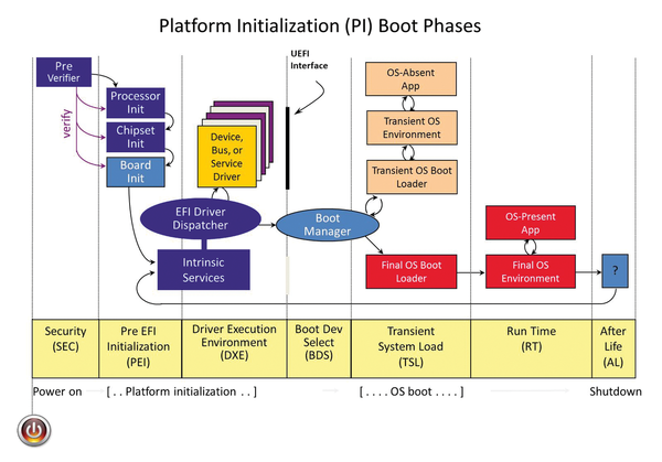
For an authoritative outline, read the EDK II Build Specification’s short boot-sequence section:
The EDK II Build Specification gives you a compact reference for the phases and their responsibilities. Read it once for the overall progression, then use the phase descriptions to check what each stage hands to the next.
In “2.3 Boot Sequence,” read “2.3.1 Security (SEC),” from SEC responsibilities. Continue through “2.3.2 Pre-EFI Initialization (PEI),” especially PEI memory setup. In “2.3.3 Drive Execution Environment (DXE)” (the page uses “Drive” in this heading; the phase is normally called Driver Execution Environment), read the DXE handoff. Finish with “2.3.4 Boot Device Selection (BDS),” from BDS responsibilities, and the opening of “2.3.5 Transient System Load (TSL) and Runtime (RT),” from the loader description. Focus on the increasing capabilities available at each stage, rather than memorizing every component name.
SEC and PEI: working before normal memory is ready
SEC (Security) is the first PI phase in this typical sequence. Its immediate job is practical: handle the restart event, establish a temporary place for early code to work, and pass essential information to PEI. Some x86 implementations use processor cache as temporary RAM at this point. SEC cannot assume that ordinary system RAM or a complete UEFI environment already exists—those are things the boot process has yet to establish.
The word Security needs care. PI documentation describes SEC as serving as a root of trust, but the phase name alone does not prove that all firmware code has been authenticated. Whether early code is protected depends on the platform’s actual hardware and firmware security mechanisms. We will examine roots of trust later; for this boot trace, remember SEC primarily as the stage that creates a minimal working environment.
PEI (Pre-EFI Initialization) uses that limited environment to bring up crucial platform resources—most importantly, permanent system memory. PEI modules can also perform early processor and chipset initialization. Once memory is available, later firmware can run with far fewer restrictions than SEC and early PEI faced.
PEI also records what it has discovered in Hand-Off Blocks (HOBs). Think of a HOB list as structured handoff data: it can describe such things as available memory and firmware-volume locations so that DXE does not have to start its understanding of the platform from nothing. The distinction is between initializing a resource and communicating its state to the next phase. PEI does both.
For a more detailed explanation of this transition, read the PEI tasks and the beginning of the DXE discussion in UEFI is the New BIOS from Leviathan Security:
This article expands the compact specification outline into an explanation of why PEI and DXE do different kinds of initialization. Use it to connect permanent memory and HOBs to the larger environment that DXE builds.
In “Pre-EFI Initialization (PEI),” start where the article says PEI prepares for DXE and read the PEI tasks; stop at the end of the HOB-list bullet, before the recovery-mode bullet. Then, in “Driver Execution Environment (DXE),” read the DXE setup, stopping before the figure and sample program. Focus on what becomes possible because PEI established memory.
There is no contradiction in saying that PEI initializes hardware and that DXE initializes hardware too. PEI does enough early work to make the platform and permanent memory usable for the next stage. DXE can then build on that work and support a much broader set of devices and firmware functions.
DXE: bringing up the UEFI environment
DXE (Driver Execution Environment) receives the platform-state information prepared earlier and brings up the richer firmware environment. Its core and dispatcher execute suitable DXE drivers, which can initialize devices and supply capabilities needed for boot—for example, access to storage or console output. The term driver here means firmware code running before the OS has taken control, not an ordinary Linux or Windows device driver.
DXE also establishes central UEFI facilities, including the UEFI System Table, Boot Services, and Runtime Services. At this point, firmware and boot software have interfaces for tasks such as working with devices and loading executable images. We will distinguish Boot Services from Runtime Services precisely in a later lesson. For now, the important point is that DXE turns a minimally initialized platform into an environment capable of finding and launching boot software.
This is why the handoff from PEI matters. Without suitable memory and knowledge of the platform’s state, DXE could not simply begin operating as though a fully prepared computer already existed.
BDS and the OS loader: selecting and starting a boot path
Once the needed DXE drivers have run, control passes to BDS (Boot Device Selection). BDS is where the firmware’s boot manager attempts configured boot selections. It may finish preparing consoles or load drivers needed for a selection. On a typical installation, a boot entry ultimately identifies a UEFI executable file on an EFI System Partition—for example, an OS bootloader. We will examine the partition and boot-entry details separately; here, the key job of BDS is choosing and launching a viable boot option.
Suppose a machine has both an installed Linux system and bootable USB media. Earlier phases make it possible to access memory, devices, and UEFI boot facilities. BDS is the stage that attempts an appropriate configured selection; it is not the stage that initializes RAM from scratch. If a selected path is unavailable, firmware may attempt another option according to its configuration.
The selected OS loader then runs in the pre-OS UEFI environment. A Linux bootloader such as GRUB, for example, can continue the work of locating and starting the OS kernel. This period is sometimes called Transient System Load (TSL). The loader is not yet the normally running OS: the kernel still needs to take control.
One timing detail is worth getting right in a security interview. Launching a loader does not itself end UEFI Boot Services. During the later handoff to the OS, the boot path calls ExitBootServices(); afterward, the OS cannot use those boot services. Some Runtime Services can remain available to the OS. You do not need to know their APIs yet, but avoid saying that BDS automatically calls ExitBootServices() the moment it selects a loader.
The trace you should be able to explain
A concise account sounds like this:
“After an x86 processor resets, it begins executing platform firmware code. SEC handles the early restart environment and provides temporary working memory. PEI performs essential early platform initialization, especially bringing up permanent RAM, and passes information about the platform to DXE in HOBs. DXE runs firmware drivers and establishes the UEFI environment and services needed to boot. BDS attempts a configured boot selection and launches a UEFI executable, typically an OS loader. The loader prepares the OS kernel, and the boot path eventually exits UEFI Boot Services as the OS takes control.”
Notice the logic behind the order: SEC can run with very little; PEI makes permanent memory available; DXE uses it to provide broad firmware capabilities; BDS uses those capabilities to start the chosen loader. If you can explain that dependency, the phase names become much easier to retain.
Key takeaways
A typical x86 UEFI boot starts at a firmware-mapped reset vector, then progresses through increasingly capable PI phases. SEC establishes a minimal environment; PEI initializes essential resources and hands off platform information; DXE brings up drivers and UEFI facilities; BDS selects and launches a boot option; and the OS loader prepares the kernel for takeover. “Security” in SEC is not, by itself, a claim that Secure Boot or another protection is enabled.
Next, we will look more closely at the firmware components behind this trace—firmware volumes, executable modules, drivers, and UEFI applications—and where they fit during initialization.