Hello! Welcome back to our work on the rotary mechanism project.
In our last session, you designed the central support plate, which acts as the structural backbone for our mechanism by precisely locating the input and output shafts. This was a crucial step in moving from individual components to an integrated system.
Today, we will build upon that foundation. Our learning outcome is to model the mechanism housing, applying DFM principles for stiffness and manufacturability. We will design the enclosure that protects the belt and pulleys, but more importantly, we'll do this by thinking like a professional engineer, balancing structural performance with the practical constraints of manufacturing. This lesson is all about making a part that is not only strong but also smart and economical to produce.
1. The "Why" Before the "How": An Introduction to DFM
Before we jump into CAD, it's essential to understand the mindset behind Design for Manufacturing (DFM). In industry, a design is only successful if it can be produced reliably, on time, and within budget. DFM is the practice of designing products with the manufacturing process in mind from the very beginning.
Your experience with FMEA has already introduced you to thinking about failure, and DFM is a similar proactive approach, but focused on production.
To start, let's watch a brief clip that powerfully illustrates the financial impact of good DFM.
Top Design Tips & Manufacturing Processes for Mechanical Engineers | DFM Guide
The video 'Top Design Tips & Manufacturing Processes for Mechanical Engineers' from the channel Engineering Gone Wild opens with a compelling, real-world example of how a simple design change, guided by DFM, can save a company millions of dollars. This highlights why DFM is such a valued skill.
Watch the first 2 minutes and 35 seconds of the video. Pay attention to the core argument: DFM is what separates a good engineer from a great one because of its direct impact on cost.
Now, let's explore the fundamental principles that guide DFM. The following reading provides a concise, structured overview.
1: Design for Manufacturing (DFM)
The article 'Design for Manufacturing (DFM)' from LibreTexts Engineering offers an excellent summary of the core concepts.
Please read the sections 'Introduction to Design for Manufacturing' and 'Key Principles of DFM'. As you read, think about how these principles might apply to a housing. Then, skim the 'Case Study: DFM Optimization of a Gearbox Housing' to see a practical application very similar to our task today.
2. Designing for Stiffness: Using Ribs Effectively
Our housing needs to be rigid enough to maintain the alignment of the shafts under the tension of the belt drive. A common mistake is to simply make the walls thicker, which adds significant weight and material cost. A much more efficient method is to add ribs.
Ribs are thin, wall-like features that dramatically increase a part's stiffness with minimal material addition. However, they must be designed correctly to be effective and manufacturable, especially for processes like injection molding or casting.
The image below shows a housing that uses ribs (the internal cross-braces) to add stiffness.

Let's dive into the specific design rules for creating effective ribs.
The article 'Rib Molding Design Techniques' from JaiRaj Group provides a set of clear, actionable rules for designing ribs for plastic parts. These guidelines are industry-standard and directly applicable to our design.
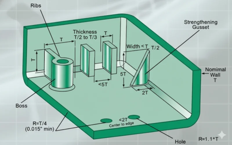
Read the section 'Rib Molding Design Factors Every Procurement Team Must Know'. Focus on the key parameters: Thickness, Height, Spacing, and Draft Angle. Note the recommended values, which are often defined relative to the part's nominal wall thickness.
Here is a helpful visual summary of these DFM rules for ribs and other common features.
3. Designing for Manufacturability: Process Constraints
To apply DFM, we must have a manufacturing process in mind. While our one-off project could be CNC machined, designing it as if it were an injection-molded plastic part is an excellent exercise for your portfolio. This is a very common scenario for producing housings in high volumes.
Let's learn the key constraints of injection molding and CNC machining, as these will directly influence our CAD model.
Top Design Tips & Manufacturing Processes for Mechanical Engineers | DFM Guide
Let's return to the 'Top Design Tips' video. The next sections provide a fantastic overview of the constraints associated with CNC machining and injection molding.
Please watch two segments: CNC Machining Constraints (08:00 - 11:20): Pay close attention to the discussions on internal corners, thin walls, and tool access. Injection Molding Constraints (19:25 - 21:56): Focus on the importance of uniform wall thickness, draft angles, and avoiding undercuts. Notice the overlap in some principles (like fillets in corners) and the unique constraints of each process.
Test your understanding!
A junior designer creates a plastic housing with sharp, 90-degree internal corners. Why might this cause problems for both CNC machining and injection molding?
Show answer
- For CNC Machining: A standard milling tool is cylindrical and cannot create a perfectly sharp internal corner. It will always leave a radius. To create a sharp corner would require a secondary, more expensive process like EDM.
- For Injection Molding: Sharp internal corners create stress concentrations, making the part weaker and prone to cracking. They can also restrict the flow of molten plastic into the mold. Good practice dictates adding a fillet (radius) to all internal corners.
4. Your Task: Modeling the Housing in Onshape
Now it's time to apply these principles. Your task is to model a two-part housing that encloses the belt drive, using the support plate from the last lesson as the central structure.
1. Set up the Assembly Context:
- Open the assembly you created in the last lesson, which contains the two shafts, pulleys, and your support plate.
- If you haven't already, add a Belt feature to connect the two pulleys. You can find this in the assembly toolbar. This will give you a visual reference for the enclosure.
2. Model the Housing Base (In Context):
- Start a "Create Part Studio in Context" from your assembly.
- The goal is to build the "bottom" half of the enclosure.
- Create a sketch on the front face of your existing support plate.
- Use the Extrude tool to build up the outer walls around the belt and pulleys. Make them tall enough to enclose about half of the mechanism.
- Use the Shell command to hollow out the part, creating a uniform wall thickness (e.g., 3 mm). This is a critical DFM step.
- Use the Draft command to apply a small draft angle (1-2 degrees) to the inside and outside vertical walls. This is essential for mold release.
- Use the Fillet command to add radii to all the sharp internal and external corners. This helps with stress distribution and manufacturability.
3. Add Stiffness with Ribs:
- Now, let's reinforce the large, flat walls of the housing.
- Watch this short Onshape tutorial to understand how the
Ribtool works. It's a powerful feature that automates the creation of these complex shapes.
The video 'Rib Command EXPLAINED' from Onshape is a focused tutorial on how to properly use this specific feature. It covers common mistakes and the different options available.
Watch the sections from 01:09 to 03:37. This will show you how the rib extends to the part and, crucially, why the sketch for the rib must be created correctly to avoid errors.
- Create a new sketch on a plane that bisects your housing (e.g., the Top Plane).
- Draw lines where you want to add ribs. A simple cross or parallel pattern on the largest faces is a good start.
- Use the Rib command, selecting your sketch lines. Set the thickness according to the DFM rules (e.g., 50-70% of your 3 mm wall, so ~1.5-2 mm).
4. Model the Housing Cover (Optional, if time permits):
- Create a second new part that will act as the cover. You can model this in the same Part Studio.
- The cover should be a simpler part that mates to the top of the housing base. You can add a lip/groove feature to help align the two halves.
- Add clearance holes for fasteners that will hold the two halves together.
Conclusion
Great work today. You've tackled a task that is at the heart of mechanical product design: creating a functional part that is also designed for efficient manufacturing and assembly. This is exactly the kind of practical, process-oriented skill that makes a strong portfolio piece.
Key Takeaways:
- Design for Manufacturing (DFM) is a proactive mindset that integrates production constraints into the design process to reduce cost and improve quality.
- Ribs are a structurally efficient way to add stiffness to a part without adding excessive mass or material cost.
- DFM rules like uniform wall thickness, draft angles, and corner radii are driven by the constraints of specific manufacturing processes like injection molding and CNC machining.
- Onshape tools like Shell, Draft, and Rib are designed to help you efficiently implement these DFM principles in your models.
Preview of the Next Lesson:
We now have all the major custom components for our rotary mechanism: the shafts, the support plate, and the housing. In the next lesson, we will integrate all parts, including bearings and fasteners, into a complete assembly. This will involve organizing our final top-level assembly, adding standard hardware from Onshape's library, and ensuring everything fits together as intended.