Hello! Welcome back.
In the last few lessons, you've done an excellent job modeling all the custom and structural parts for our linear actuator project. We have the drive components (motor and screw), the guidance system (rails and bearings), the custom brackets, and the structural frame. Now it's time to put it all together.
Today's learning outcome is to integrate all parts into a top-level assembly with appropriate mates. This is a pivotal step where our collection of individual parts becomes a functional virtual mechanism. Your experience in mechanical design will make the concepts of constraining motion familiar, but we'll focus on how Onshape's modern approach makes this process efficient and powerful.
We will cover:
- The core principles of Onshape's mating system.
- A step-by-step workflow for building a robust assembly.
- Applying different mate types to define both static relationships and dynamic motion.
- Using a mate relation to simulate the lead screw's action.
Let's begin assembling your design.
1. The Onshape Mating Philosophy: Connectors and Degrees of Freedom
Before we start clicking, it's important to understand how Onshape handles assemblies, as it's different from some older CAD systems. Instead of mating geometric faces and edges directly, Onshape uses Mate Connectors.
A Mate Connector is essentially a coordinate system (an origin with X, Y, and Z axes) that you can place on a part. A Mate then defines the relationship between two of these connectors, specifying which degrees of freedom (DoF) are allowed between them. As you know from kinematics, any rigid body in space has 6 DoF: 3 translational (movement along X, Y, Z) and 3 rotational (rotation about X, Y, Z). Every mate you apply works by constraining one or more of these DoFs.
This video gives an excellent conceptual breakdown of this philosophy.
How assembly mates work in Onshape
Watch this video from Evan Reese to understand the fundamentals of mate connectors and how they relate to the six degrees of freedom. This will provide a solid foundation for the rest of the lesson.
Please watch the first part of the video, from the beginning to 02:30. Focus on the explanation of a mate connector as a coordinate system and the breakdown of the six degrees of freedom.
2. Assembly Workflow: Building from a Fixed Base
A robust assembly starts with a solid foundation. The standard professional workflow is to bring in your main structural component first and lock it in place. All other parts are then mated relative to this fixed base.
Your Task: Start the Assembly
- In your Onshape document, create a new Assembly tab.
- Click the
Insertbutton on the toolbar. Navigate to your Part Studios and insert the structural frame you created in the last lesson. - Click the green checkmark to place the frame at the assembly's origin.
- Now, right-click the frame in the Instances list on the left and select
Fix. You'll see an icon appear next to its name, indicating it's locked in space. This prevents the entire assembly from floating around.
3. Applying Mates: From Static to Dynamic
With the frame fixed, we can begin adding the other components and defining their relationships. We'll work through the main mate types needed for our project. The Onshape Help documentation provides a comprehensive reference for all mate types.
This is the official Onshape documentation for Mates. It's a great resource to have bookmarked. You don't need to read it all now, but it's good to know where to find detailed information.
Briefly skim the introduction to understand Onshape's philosophy, and look at the 'Mate indicators' section to see the symbols for different mates. We will be using Fastened, Slider, and Revolute mates primarily.
Let's see a practical demonstration of the basic assembly process.
Onshape Assemblies 101 - Beginner and advanced examples
This video from Teaching Tech demonstrates the basic process of inserting parts and applying common mates like Fastened and Revolute.
Watch from 04:24 to 07:55. This segment covers inserting parts, applying a Fastened mate to lock parts together, and using a Revolute mate to allow rotation. Pay attention to how the 'mate connectors' appear automatically as you hover over geometry.
Your Task: Assemble the Components
Follow these steps in your Onshape assembly. The hotkey for the Mate tool is M.
-
Mount the Guide Rails (
FastenedMate):- Insert your two linear guide rails.
- Use the
Fastenedmate to attach them to the top surface of your frame. AFastenedmate removes all 6 DoF, rigidly connecting two parts. - Pro Tip: To mate the rail's bottom face to the frame's top face, you can select the center of each face's mate connector. If you want to align it by an edge, you can select mate connectors on the edges.
-
Add the Bearing Blocks (
SliderMate):- Insert two bearing blocks.
- Use the
Slidermate to attach one block to each rail. ASlidermate allows for one degree of freedom: translation along the Z-axis of the mate connector. - Select the mate connector in the center of the bore of the bearing block and the mate connector on the edge or face of the rail. Onshape is smart enough to create a sliding relationship along the rail's length.
- After applying the mate, try dragging the blocks. They should slide freely along the rails but shouldn't be able to lift off or twist.
-
Install the Lead Screw (
RevoluteMate):- Insert your lead screw, lead screw nut, and the motor/bearing mounting brackets.
Fastenthe brackets to the frame.- The lead screw needs to be held by the bearings in its mount but be free to rotate. Use a
Revolutemate between the shaft of the lead screw and the bore of the bearing/bracket that supports it. This allows only one DoF: rotation.
4. Simulating the Actuator: The Screw Relation
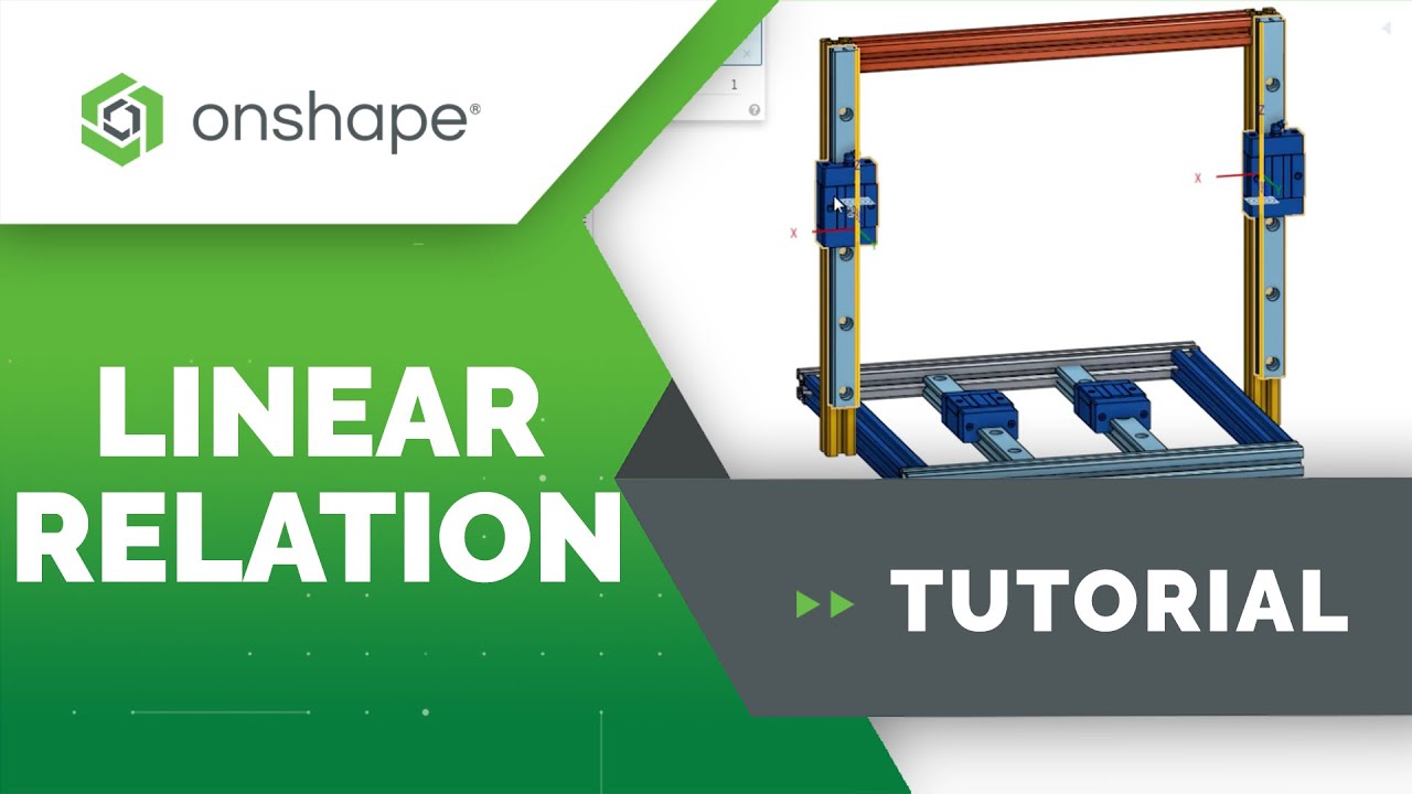
Now for the most important part: linking the screw's rotation to the linear motion of the nut. We do this with a Mate Relation.
First, we need a moving platform. Insert a simple plate (you can model a basic rectangular plate in a new Part Studio if you haven't already). Fasten this plate to the top of your two bearing blocks and Fasten the lead screw nut to the underside of this plate. Now, this entire platform should slide back and forth with the bearing blocks.
Next, we'll create the screw mechanism.

Your Task: Create the Screw Relation
- Find the
Screw relationicon in the assembly toolbar. It looks like a screw and is typically grouped with other mate relations. - The dialog will ask for two mates to relate:
- Mate 1: Select the
Revolutemate you created for the lead screw. - Mate 2: Select one of the
Slidermates you created for the bearing blocks.
- Mate 1: Select the
- Distance per revolution: This is the critical value. Enter the lead of your lead screw. For example, if your screw is a TR8x8, the lead is 8 mm. Make sure your units are correct.
- Click the green checkmark.
Now, test your assembly! Click and drag the lead screw to rotate it. The entire platform should slide smoothly along the guide rails. You've just created a fully functional virtual mechanism.
Test your understanding!
You've successfully created the Screw relation. When you rotate the screw clockwise, the carriage moves to the right. The design requirement, however, is for it to move to the left. What is the quickest way to fix this?
Show answer
The quickest way is to edit the Screw relation feature. In the dialog box, there is a "Reverse direction" checkbox or icon. Toggling this will invert the relationship between the rotational and linear motion without needing to redefine any of the underlying mates.
Conclusion
Fantastic work today! You have successfully transitioned from a folder of parts to a dynamic, functional assembly. This is the moment in the design process where you can truly validate the mechanical concept and see it in motion.
Key Takeaways:
- A robust assembly starts with a fixed base component to ground the design.
- Onshape's mate connectors and degrees-of-freedom approach provides a powerful way to define relationships between parts.
- Standard mates like
Fastened,Revolute, andSliderhandle the majority of assembly requirements. - Mate Relations, like the
Screwrelation, are used to create complex kinematic links between different motions in the assembly.
Preview of the Next Lesson:
With a complete 3D assembly, the next logical step in a professional workflow is creating the documentation. In our next lesson, we will create an assembly drawing in Onshape and place standard orthographic and isometric views. We will also generate our first preliminary Bill of Materials (BOM), a critical document for manufacturing and procurement.