Hello! Welcome back.
In our last lesson, you designed a sheet metal bracket, focusing on the tools and manufacturing considerations within Onshape. This is a critical skill for creating structural components. But how do we know if the bracket is strong enough?
Today, we move to the next logical step in the design process: validation. Our learning outcome is to set up a basic stress analysis in Onshape, including applying materials, loads, and constraints.
Given your background in mechanical engineering and FEA, the underlying concepts of stress, strain, and boundary conditions will be familiar. Our focus today will be on applying that knowledge within Onshape's integrated simulation environment. You'll learn the specific workflow for taking a part from a 3D model to a component with a defined analysis, ready for interpretation. This is a core competency for modern design engineers and a crucial part of the "real-life engineer's work" you're aiming to simulate for your portfolio.
1. What is Onshape Simulation?
Onshape Simulation is a structural analysis tool built directly into the assembly environment. It's designed for designers and engineers to get quick feedback on the mechanical performance of their parts without leaving the CAD interface. This integrated approach is a significant shift from traditional workflows that often require exporting models to separate, specialized analysis software.
To get a feel for the philosophy behind this tool, let's watch a brief overview from Onshape.
Onshape Simulation Overview and Demo
This video, "Onshape Simulation Overview and Demo," explains why this tool was created for designers. Pay attention to how it simplifies the conventional analysis workflow.
Watch from 07:56 to 09:51. The presenters contrast the conventional, multi-step simulation workflow with Onshape's streamlined approach. Notice that defining part interactions (mates) is part of the design process, not a separate analysis step.
As you saw, the goal is to make analysis a natural part of design. The key takeaway is that Onshape leverages the work you've already done in creating an assembly—defining mates—to automatically understand how parts are connected.
2. The Three Pillars of a Simulation Setup
At its core, setting up any linear static structural analysis, whether in Onshape or another FEA package, requires three fundamental inputs. You must tell the software:
- Constraints: How is the part or assembly held in place? What can't move?
- Materials: What is it made of?
- Loads: What forces, pressures, or accelerations is it subjected to?
We will now walk through how to define each of these three pillars in Onshape.
3. Step 1: Define Constraints (The "Fixed" Part)
In the real world, your bracket would be bolted to a larger frame or structure. For a simulation, we need to define this "ground" or fixture. In Onshape, this is done by fixing at least one part in the assembly.
An important rule: Onshape Simulation only runs in an Assembly tab. Even if you want to analyze a single part, you must place it into an assembly.
The Basic Requirements
Before you can apply any loads, your assembly must meet two conditions:
- At least one part instance must be fixed. This part acts as the anchor for the simulation.
- All other parts in the simulation must have a material assigned.
Let's read the official documentation that outlines this setup.
The Onshape Help documentation for "Simulation" provides a clear, step-by-step guide. We will refer to this document throughout the lesson.
First, read the two paragraphs under the main heading that begin with "Before creating the simulation...". Then, skim the section titled "Basic workflow: Create and simulate a load" and read Step 1, which describes how to fix an instance in the assembly.
A common scenario is wanting to test a single component, like the bracket you designed in the last lesson. To do this, you would create a new assembly, insert your bracket, and also insert a small, simple "ground" part (e.g., a small block). You would then fix the ground block and use a Fasten Mate to connect your bracket to it. The fixed ground block will be excluded from the results, allowing you to analyze the bracket itself. The article "Tech Tip: How to Simulate a Standalone Part in Onshape" (ID: LINK) details this exact process if you'd like to explore it further.
4. Step 2: Assign Materials
An analysis is meaningless without accurate material properties. For a linear static analysis, the key properties are:
- Young's Modulus (Modulus of Elasticity): Defines the material's stiffness.
- Poisson's Ratio: Describes the deformation in directions perpendicular to the applied force.
- Tensile Yield Strength: The stress at which the material begins to deform permanently. This is used to calculate the Factor of Safety.
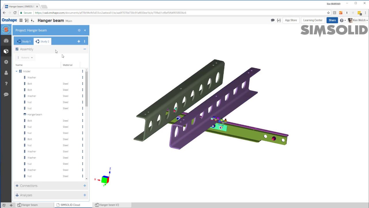
You can assign materials either in the Part Studio or directly in the Assembly's Bill of Materials (BOM) table. Onshape's built-in material library includes common metals and plastics with these properties already defined.
You can also create your own custom materials, which is essential for professional work where you might be using a specific alloy not in the standard library.
Onshape Simulation Overview and Demo
This short clip from the "Onshape Simulation Overview and Demo" video shows where you can define custom material properties.
Watch from 47:11 to 48:18. Note the fields available when creating a custom material, including Young's Modulus, Poisson's Ratio, and various strength values. This demonstrates that you have full control over the inputs for your analysis.
5. Step 3: Apply Loads
With the part constrained and its material defined, the final step is to apply the loads it will experience in service. Onshape provides several load types.
Let's return to the Onshape "Simulation" help page to review the available load types.
Read the section titled "Simulation load tools." This provides a brief description of the six available load types: Force, Moment, Bearing, Pressure, Acceleration, and Angular Velocity. For today, we will focus on the most common one: Force.
To apply a force, you select the part you want to load, define the direction and magnitude, and specify the region where the force is applied (either the whole body or specific faces).

The load direction is typically defined using a mate connector, giving you precise control over the X, Y, and Z components of the force vector.
6. Guided Practice: Setting Up Your First Analysis
Now, let's put it all together. The following resource provides a complete, step-by-step workflow for setting up an analysis on a caliper bracket. Follow these steps in Onshape to get hands-on experience. You can use the bracket you designed in the previous lesson or create a simple L-bracket for this exercise.
We will now follow the "Basic workflow" guide in the Onshape Help documentation. This is an excellent, practical tutorial that covers every step we've discussed.
Carefully read and follow the steps in the section titled "Basic workflow: Create and simulate a load". This will guide you through: Fixing an instance (or a 'ground' part). Assigning materials to the part you want to analyze. Applying a Force load with a specific direction and magnitude. Showing the results to run the simulation. Don't worry about interpreting the results in detail just yet; focus on correctly completing the setup process.
Once you click "Show results," Onshape will begin solving. You'll see a color plot appear on your model, which represents the stress distribution.
Test your understanding!
Imagine you apply a force to your bracket, but when you run the simulation, the entire part flies off into space and the simulation fails. Based on the "three pillars" of simulation setup, which of the three required inputs did you most likely forget or misconfigure?
Show answer
You most likely forgot to properly constrain the model. If no part is fixed, or if the part you are loading is not properly mated to a fixed part, it becomes a "free body." When a force is applied to a free body, it will accelerate indefinitely according to Newton's second law (F=ma), causing the simulation to fail. This is a very common beginner's mistake.
Conclusion
Congratulations! You have successfully set up your first structural analysis in Onshape. You now understand the practical workflow for taking a CAD model and preparing it for virtual testing.
Key Takeaways:
- Setting up a basic stress analysis requires defining three things: constraints (fixed parts), materials, and loads.
- Onshape simulation runs within the Assembly environment and cleverly uses mates to define connections between parts.
- The fundamental workflow involves:
- Placing your part in an assembly.
- Fixing a ground part and mating your component to it.
- Assigning a material with the necessary properties (Young's Modulus, Yield Strength).
- Applying a load (like Force) using the tools in the assembly toolbar.
Preview of the Next Lesson:
Running the simulation is only half the battle. The real engineering value comes from understanding what the results mean. In our next lesson, we will dive deep into the results you just generated. You will learn to interpret FEA results to evaluate stress, displacement, and factor of safety in a component, allowing you to make informed decisions to improve your design.