Hello! Welcome to our next session.
In the last lesson, we focused on transforming 2D sketches into 3D solid parts using parametric, feature-based modeling. You learned how to create a "recipe" for a part and even how to model multiple parts within a single Part Studio.
Today, we'll take those individual parts and bring them together into a working mechanism. This lesson addresses the learning outcome: Create multi-part assemblies using standard mates. We will move from the Part Studio to the Assembly tab in Onshape. You'll learn how to define the spatial relationships between components using Onshape's unique mating system. This is the step where your static parts come to life and form the functional mechanical systems you'll feature in your portfolio.
1. The Assembly Environment and the Onshape Mating Philosophy
An assembly is a collection of parts positioned relative to one another. In a professional workflow, this is where you verify fit, check for interference, and define mechanical motion. Onshape handles this process with a powerful and efficient system based on Mates.
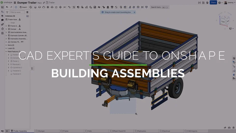
Unlike some traditional CAD systems where you might apply multiple constraints (e.g., align two faces, make two edges concentric, set a distance) to position one part, Onshape typically uses a single Mate to define the relationship between two parts. This is much faster and easier to manage.
To understand how this works, let's look at the two core concepts: Degrees of Freedom and Mate Connectors.
Degrees of Freedom (DOF)
As you'll know from your mechanical engineering background, any unconstrained object in 3D space has six degrees of freedom:
- Translation along the X, Y, and Z axes.
- Rotation about the X, Y, and Z axes.
Mating is simply the process of removing these degrees of freedom to achieve the desired motion. A Fastened mate removes all six DOFs, rigidly locking two parts together. A Revolute mate (like for a hinge) removes five, leaving only one rotational DOF.
Mate Connectors
Instead of mating geometric entities like faces or edges directly, Onshape uses a special entity called a Mate Connector. A Mate Connector is essentially a local coordinate system (with an origin and X, Y, Z axes) that you can place on your part. A Mate then defines the relationship between the coordinate systems of two Mate Connectors.
This video provides an excellent explanation of this fundamental concept.
How assembly mates work in Onshape
This video from Evan Reese, titled 'How assembly mates work in Onshape', breaks down the core philosophy behind Onshape's mating system. It's crucial for understanding how to approach assemblies in Onshape.
Watch the first 2 minutes and 30 seconds. Pay close attention to the explanation of a Mate Connector as a coordinate system and how mates are 'pre-packaged sets of degrees of freedom'.
This approach is one of Onshape's key strengths. To get a quick sense of why it's so efficient, take a few minutes to read the first two sections of this article from Onshape.
Build Assemblies Faster with Onshape Mates
This blog post, 'Build Assemblies Faster with Onshape Mates', explains the benefits of Onshape's mating system and introduces the concept of Mate Connectors.
Read the sections 'Mates: Building Assembly Relationships' and 'Mate Connectors'. This will reinforce why you'll be creating far fewer mates in Onshape compared to other systems.
2. A Tour of the Standard Mates
Onshape provides a set of standard mates that cover the vast majority of mechanical design scenarios. Each one allows for a specific type of motion. We'll focus on the four most common ones.
As you watch the following demonstrations, notice how each mate is defined by selecting a Mate Connector on each of the two parts you want to connect. Onshape automatically creates these "implicit" mate connectors for you as you hover over geometry.
Onshape Assembly Mates (Overview)
This video from the official Onshape YouTube channel, 'Onshape Assembly Mates (Overview)', provides clear, concise demonstrations of the most common mate types.
Watch the video from the beginning to 03:51. It will cover the following four mates. You can pause after each section to absorb the concept. Fastened Mate (0:00 - 1:18): Removes all 6 DOFs. Use this to rigidly attach parts, like bolting a bracket to a frame. Revolute Mate (1:18 - 1:56): Allows 1 rotational DOF. Use this for hinges, axles, and any part that pivots. Slider Mate (1:56 - 2:41): Allows 1 translational DOF. Use this for parts that slide along a linear path, like a drawer or a guide block on a rail. Cylindrical Mate (2:41 - 3:51): Allows 1 rotational and 1 translational DOF. Use this for a shaft that can both spin and slide within a bushing or hole.
While these four mates will handle many of your needs, Onshape provides others for more specific situations (Planar, Pin Slot, Ball, etc.). You can find a complete list with descriptions in the Onshape Help documentation, which is an excellent resource to bookmark for future reference.
The official Onshape Help documentation for Mates is a comprehensive guide to all mate types and options.
You don't need to read this entire document now, but skim two sections to familiarize yourself with it: 'Concepts': Scroll to the bottom and review the 'Concepts' section. It provides a great summary with visual hints for each mate type. 'Mate dialog': Scroll back up and quickly review the description of the mate dialog options, like 'Flip primary axis' and 'Reorient secondary axis'. These are essential for correctly orienting your parts.
Test your understanding!
You are designing a simple piston and cylinder mechanism.
- How would you mate the piston head to the inside of the cylinder barrel to allow it to move back and forth but not rotate?
- How would you mate a wrist pin to the piston head so the connecting rod can pivot on it?
Show answer
- A Slider Mate is the ideal choice. It provides the single translational degree of freedom needed for the piston to move along the cylinder's axis while preventing any rotation.
- A Revolute Mate would be used to connect the connecting rod to the wrist pin. It allows the single rotational degree of freedom for the pivoting motion. The pin itself would likely be attached to the piston with a Fastened Mate.
3. Practical Application: Building Your First Assembly
Now, let's apply these concepts. The general workflow for creating an assembly is:
- Create a new Assembly tab.
- Insert the parts you modeled in your Part Studio.
- Fix one base component to the origin. This provides a static reference for the rest of the assembly.
- Use mates to connect the remaining parts to the fixed part or to each other.
First, let's understand why fixing a component is so important.
How assembly mates work in Onshape
We'll return to the 'How assembly mates work in Onshape' video to understand the difference between fixing a part and mating it, and why it's best practice to have only one fixed part in your assembly.
Watch the segment from 08:51 to 09:48. This explains the importance of the 'Fix' command for establishing a stable base for your assembly.
Your Turn: Assemble a Simple Hinge
Open your "Project 1" Onshape document.
- Create a new Part Studio.
- Quickly model two simple parts:
- Part 1 (Base): A small rectangular block (e.g., 50x50x10 mm). Add a through-hole near one edge (e.g., 10 mm diameter).
- Part 2 (Lever): Another rectangular block (e.g., 100x20x10 mm). Add a matching through-hole at one end.
- Tip: Model these side-by-side in the same Part Studio. This ensures the holes are the same size.
- Create a new Assembly tab (click the '+' icon at the bottom left and select 'Create Assembly').
- Click the Insert button on the toolbar. In the dialog, select the two parts you just created from the Part Studio tab and place them in the graphics area. Click the green check to confirm.
- Right-click on the Base part in the graphics area or in the Instances list on the left and select Fix. A small icon will appear next to its name, indicating it's locked in place.
- Select the Revolute Mate from the toolbar.
- Hover your mouse over the circular edge of the hole on the Base. A number of mate connectors will appear. Click the one at the center of the hole's opening.
- Now, hover over the circular edge of the hole on the Lever and click the mate connector at its center.
- The parts will snap together. You can use the
FlipandReorientbuttons in the dialog if needed. Click the green check to accept the mate. - Click and drag the Lever part. It should now pivot around the hole, just as a hinge would.
Congratulations, you've created your first assembly!
Conclusion
In this lesson, you moved from individual parts to functional assemblies. You learned Onshape's unique and efficient approach to mating, which is fundamental to designing any mechanical system.
Here are the key takeaways:
- Assemblies define relationships: The Assembly tab is where you define how parts fit and move together.
- Mates control Degrees of Freedom (DOF): Mates work by constraining the 6 DOFs between two parts to achieve desired motion.
- Onshape uses Mate Connectors: Instead of mating geometry directly, Onshape mates are defined between local coordinate systems called Mate Connectors.
- Start with a Fixed Part: Every stable assembly should begin with one component that is
Fixedto provide an anchor. - Core Mates (
Fastened,Revolute,Slider,Cylindrical): These four mates can define a wide range of common mechanical movements.
You now have the skills to not only model parts but also to assemble them into mechanisms. In our next lesson, "Analyze the motion of an assembly using mates and relations," we will explore how to drive and examine the motion you've just enabled, allowing you to validate your design's kinematic behavior.