Introduction
Welcome to the first lesson of our module on Codebase Structural Patterns. In the previous module, we established the crucial role of Dependency Injection for decoupling components, culminating in how to implement it idiomatically in Rust using traits. Those techniques are the essential "glue" that enables the high-level architectural patterns we'll be exploring now.
Today, we will formalize your experience with application structure by dissecting the Layered Architecture. This is one of the most fundamental and widely used patterns for organizing a codebase. Our goal is to go beyond an "organic" structure and learn how to design a system with clear, deliberate layers, each with a distinct and well-defined responsibility. By the end of this lesson, you will be able to design a layered system, define the role of each layer, and understand how they communicate while maintaining low coupling.
What is Layered Architecture?
At its core, Layered Architecture is a technique for achieving Separation of Concerns. We partition the application's code into a stack of horizontal layers, where each layer is responsible for a specific aspect of the system's functionality.

While different sources might name the layers slightly differently, the underlying principle remains the same. The most critical rule governing this pattern is the Dependency Rule.
Layered Architecture for Building Readable, Robust, and Extensible ...
This article from Towards Data Science provides a great high-level overview of the core principle.
Please read the section titled Layer Relationships. The key takeaway here is the concept that dependencies flow inward. This means higher-level layers, which contain the core business logic, must remain completely ignorant of the lower-level layers that deal with infrastructure details like databases or frameworks.
This unidirectional dependency constraint is the foundation of the pattern's power. It protects your core business logic from the volatility of external concerns, making the system more maintainable, testable, and adaptable.
The Four Common Layers
To make this concrete, let's examine a common and effective four-layer model, often used in conjunction with Domain-Driven Design (DDD). We'll define each layer's responsibilities and see how they map to both a standard web application and a more specialized system, like one for industrial computer vision.
Crafting Maintainable Rust Web Apps with Layered DDD | Leapcell
This article from the Leapcell blog gives clear, concise definitions for a four-layer model.
Please read the bullet points in the section Understanding the Core Concepts. Focus on the definitions for Layered Architecture, Domain Layer, Application Layer, Infrastructure Layer, and User Interface / Presentation Layer.
Let's break these down one by one.
1. Presentation Layer (or User Interface / Interface Layer)
- Responsibility: This is the outermost layer, responsible for all interaction with the outside world. It receives input and presents output. It should contain no business logic.
- Typical Components: Web controllers (like in FastAPI or Axum), command-line interface (CLI) parsers, GUI components, and consumers for message queues.
- In Practice: The
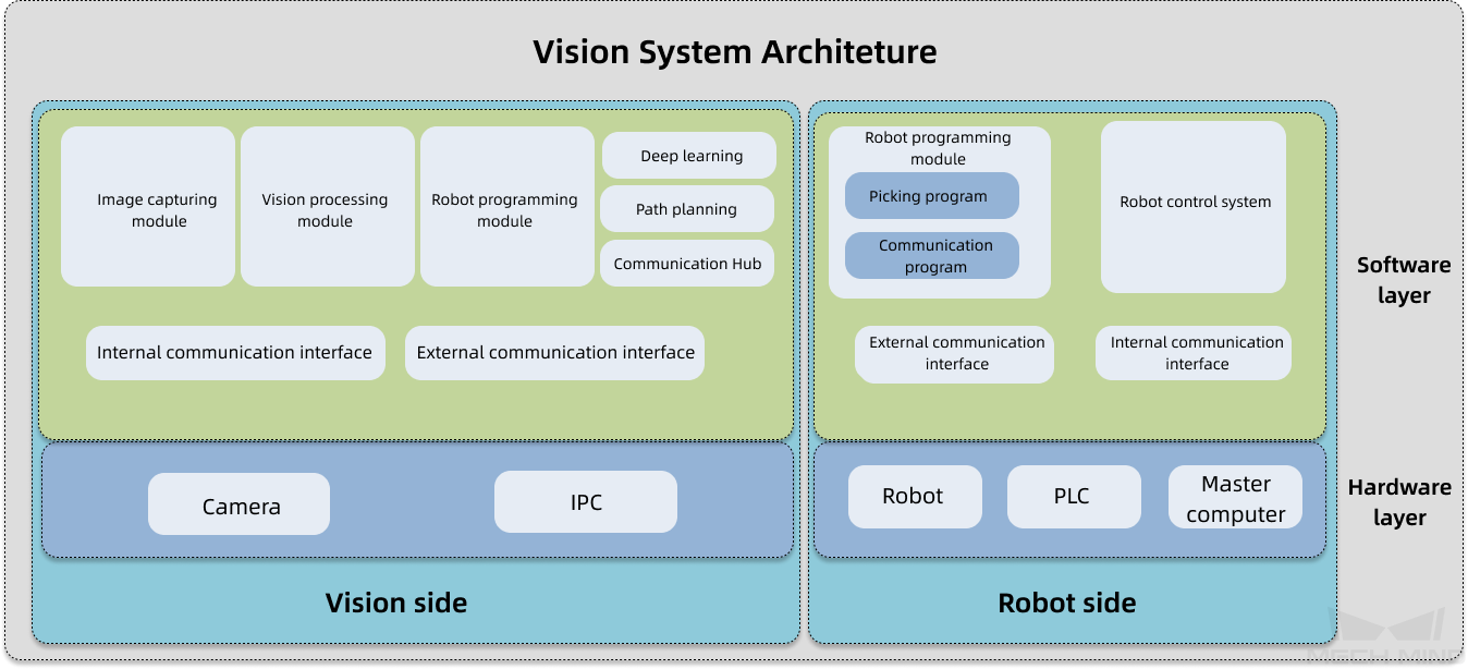
apifolder in the ArjanCodes video, containing FastAPI routers, is a perfect example of this layer. Its job is to handle HTTP details, parse incoming JSON, and then delegate the real work to a lower layer. - Computer Vision Context: In a vision system, this layer could be a web endpoint that receives an image for processing, a component that listens for a trigger from a PLC, or a service that publishes results to a dashboard or another machine. In the Vision System Architecture diagram, the "External communication interface" serves this role.
2. Application Layer (or Use Case Layer)
- Responsibility: This layer orchestrates the domain logic to fulfill a specific application use case. It doesn't contain the business rules itself but knows the steps required to execute them. For example, "create a user" or "process a new order."
- Typical Components: Service classes or use case functions that are called by the Presentation Layer.
- In Practice: In the Leapcell article, the
TaskServiceis a classic Application Layer component. It orchestrates domain objects (Task,TaskDescription) and repository interfaces to perform actions likecreate_task. It represents the application's specific workflows. - Computer Vision Context: A
ProcessImageUseCasewould live here. It might be triggered by the Presentation Layer. Its job would be to call the Domain Layer to load an image into a domain-specific format, run a feature detection algorithm, and then instruct the Infrastructure Layer to save the results.
3. Domain Layer (or Business Logic Layer)
- Responsibility: This is the heart of your application. It contains the core business rules, logic, and data models that are fundamental to the problem you are solving, completely independent of how the application is presented or what database it uses.
- Typical Components: Entities (objects with identity), Value Objects (objects defined by their attributes), and Domain Services (logic that doesn't fit on an entity).
- In Practice: The
Taskentity in the Leapcell article, with its business rulemark_as_completed, is a pure domain object. It knows nothing of databases or HTTP. - Computer Vision Context: This is where your core algorithms and data structures reside. For example:
- A
CadModelstruct representing the ideal state of a part. - A
PointCloudstruct with methods for geometric transformation (.rotate(),.translate()). - An algorithm function
detect_defects(image, model)that contains the pure mathematical logic for comparison.
The "Vision processing module" in the Vision System Architecture diagram would contain significant Domain Layer code.
- A
4. Infrastructure Layer
- Responsibility: This layer provides the technical capabilities and concrete implementations for services required by the other layers. It's where all the "dirty" details of talking to the outside world live.
- Typical Components: Database repositories (e.g., a
PostgresUserRepository), clients for external APIs, message queue publishers, logging frameworks, and file system access. - In Practice: The
PgTaskRepositoryin the Leapcell article is a perfect example. It implements theTaskRepositoryinterface (defined by a more central layer) using a specific technology (sqlxfor PostgreSQL). This allows you to swap out PostgreSQL for an in-memory database for testing, or even a different SQL database, without changing any code in the Application or Domain layers.
How The Layers Interact: Dependency Inversion
You might be asking: "If the Application Layer needs to save data, but the Dependency Rule says it can't depend on the Infrastructure Layer where the database code lives, how does it work?"
This is precisely where the Dependency Injection and abstraction principles we've covered come into play. The solution is Dependency Inversion.
Instead of the Application Layer depending directly on a concrete database class, it depends on an abstraction (a trait in Rust, or a Protocol in Python). This abstraction lives with or is owned by the Application/Domain Layer. The Infrastructure Layer then provides a concrete implementation of that abstraction.
Practical Clean Architecture in Rust [with Axum Template]
This video on Clean Architecture provides an excellent visualization of how control flow differs from dependency flow, and why dependency inversion is the key.
Watch the section that walks through a request flow, from the initial request, to the point where the use case needs to interact with the database. Then, pay close attention to the explanation of the problem and the solution using a trait (a Port) from this segment. This is the mechanism that enforces the layered architecture.
Project Structure and Request Flow
These abstract layers translate directly into a physical folder structure in your projects. This organization makes it clear where new code should go and what dependencies are allowed.
Crafting Maintainable Rust Web Apps with Layered DDD | Leapcell
The Leapcell article provides a fantastic, concrete example of a layered Rust project.
Skim through the sections from Practical Layering to the end of the main function example. You don't need to read every line of code, but observe: The folder structure: application/, domain/, infrastructure/, presentation/. The Domain Layer defines the Task entity and the TaskRepository trait. It has no external dependencies. The Application Layer's TaskService depends on the TaskRepository trait, not a concrete implementation. The Infrastructure Layer provides PgTaskRepository, which implements the TaskRepository trait. The Presentation Layer (handlers) calls the TaskService. Finally, main.rs acts as the Composition Root, wiring everything together. It creates the concrete repository, injects it into the service, which is then used by the handlers.
This same pattern applies directly to Python.
Anatomy of a Scalable Python Project (FastAPI)
ArjanCodes' video on a scalable Python project demonstrates a very similar layered approach using a FastAPI application.
Watch his breakdown of the folder structure from this section. Notice the parallels: api/ is the Presentation Layer, services/ is the Application Layer, db/ is the Infrastructure Layer, and models/ contains both domain-like objects and data transfer objects. Listen to his summary of the benefits at this timestamp. Finally, watch the explanation of how a request flows through these layers from this segment.
Conclusion
In this lesson, we have established a formal structure for organizing a codebase using Layered Architecture. By partitioning our code into distinct layers with clear responsibilities, we move from an "organic" to an engineered system design.
Key Takeaways:
- Layered Architecture separates an application into horizontal layers (e.g., Presentation, Application, Domain, Infrastructure).
- The Dependency Rule is paramount: dependencies must only flow inward. Higher-level, abstract layers cannot depend on lower-level, concrete layers.
- Responsibilities are key:
- Presentation: Handles I/O and interaction with the outside world.
- Application: Orchestrates domain logic to execute use cases.
- Domain: Contains the pure, framework-independent business logic and rules.
- Infrastructure: Provides concrete implementations of technical concerns (database, APIs, etc.).
- Dependency Inversion is the mechanism that makes this work, using abstractions like traits or protocols to decouple the application core from infrastructure details.
Now that you have a solid understanding of this foundational pattern, you're ready to explore variations and refinements. In our next lesson, we will look at Hexagonal Architecture (Ports and Adapters). You will see it's not a replacement for layered architecture but rather a different way of visualizing and enforcing the same core principles of separation, especially between the application's core and its external tooling.