Hello! Welcome to your next lesson in the "Generation and Transformer Fundamentals" module.
Introduction
In our last lesson, we compared coal, gas, and nuclear power stations. We saw that despite their different heat sources, they all ultimately do the same thing: use steam to spin a turbine. That spinning turbine provides the rotational mechanical energy that is the input to our electricity generation process.
This lesson directly follows on from that, addressing the learning outcome: Explain how synchronous generators convert rotational energy into three-phase AC electricity.
We will break down the magic of how that physical rotation is transformed into the electrical energy that powers the country. We'll start with the fundamental principle of electricity generation and build up to the three-phase system that is the standard for large-scale power grids.
1. The Core Principle: Electromagnetic Induction
At the heart of every large-scale generator is a principle discovered by Michael Faraday in the 1830s: electromagnetic induction. In simple terms, if you move a magnet near a coil of wire, you will generate an electrical current in that wire.
All synchronous generators, also known as alternators, are based on a refined version of this idea: instead of moving a simple bar magnet, they use a powerful rotating electromagnet.
To see this principle in action, let's start with a basic single-phase generator.
How Three Phase Electricity works - The basics explained
This video from The Engineering Mindset provides an excellent, clear explanation of how a basic AC generator works, starting from a single rotating magnet and one coil of wire.
Please watch the section from 00:39 to 04:11. Focus on how the rotating magnetic field pushes and pulls electrons in the copper coil, creating an alternating current and a characteristic sine wave.
As the video explained, the two essential parts are:
- The Rotor: The rotating part. In a power station generator, this is a powerful electromagnet, which is spun by the turbine.
- The Stator: The stationary part. This is a fixed casing that holds the coils of copper wire where the electricity is generated. These coils are often called the armature windings.
The key takeaway is that the rotation of the rotor's magnetic field induces an alternating current (AC) in the stationary stator coils. The current continuously alternates direction, creating a smooth, repeating pattern called a sine wave.
2. From Single-Phase to Three-Phase Power
The simple generator we just saw produces a single sine wave, known as single-phase power. While this is what most small devices in your home use, it's not ideal for generating and transmitting power on a national scale because the power delivery pulsates.
To create a smoother and more powerful supply, power stations generate three-phase power. The concept is surprisingly simple: instead of one set of coils in the stator, we use three.
How Three Phase Electricity works - The basics explained
Let's continue with the same video, which now beautifully illustrates the transition from single-phase to three-phase power.
Watch the segment from 04:52 to 05:59. Notice how adding a second, and then a third, coil smooths out the power delivery, creating a more constant output.
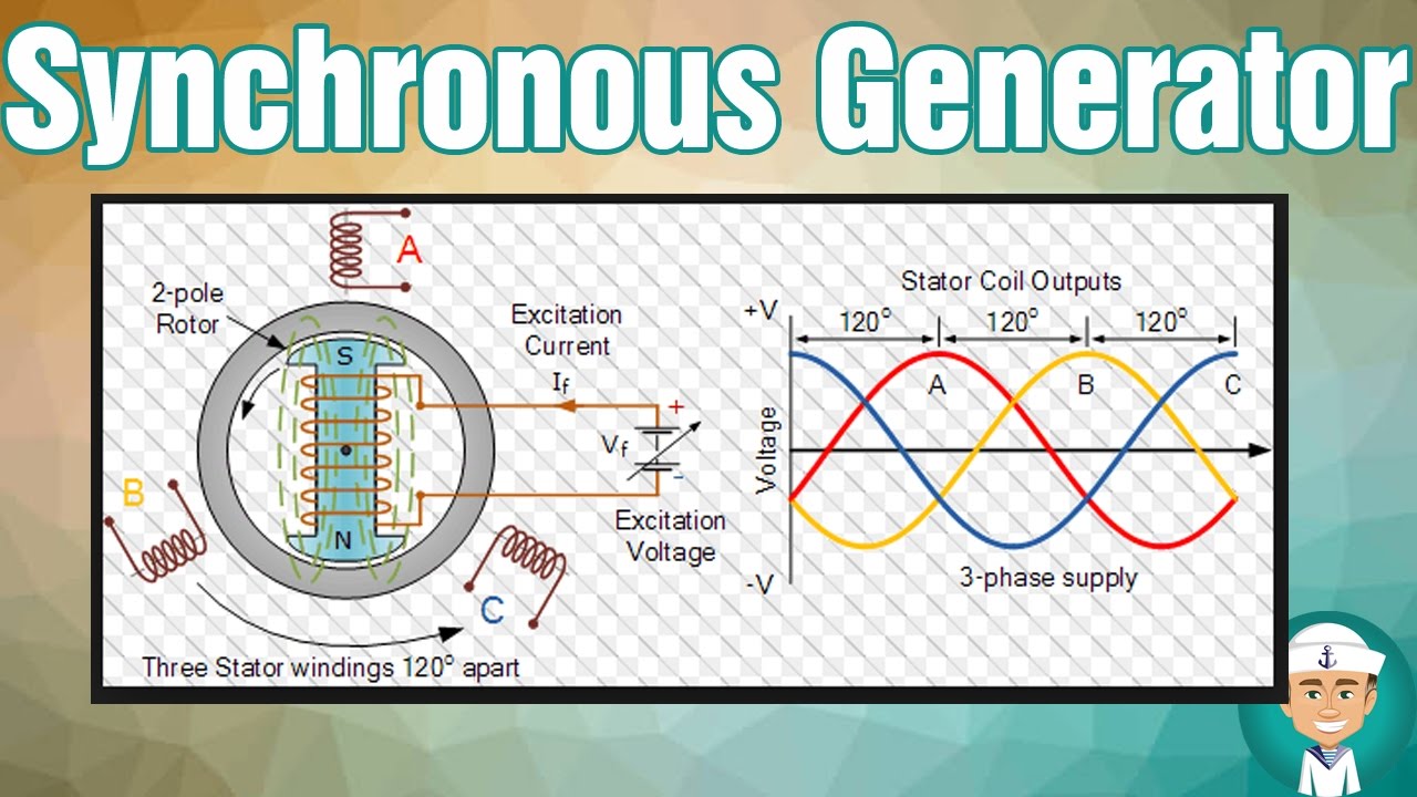
The crucial design feature is that the three sets of armature windings are physically placed 120 degrees apart from each other around the stator.
As the rotor's magnetic field spins, it passes each of the three windings in sequence. This induces a voltage and current in each winding, but because of their spacing, the three resulting sine waves are offset from each other. Each phase reaches its peak at a different moment, creating a much more continuous and balanced flow of power.
This image clearly shows the relationship between the generator's physical structure and its electrical output.
3. The Synchronous Generator in Action
Now let's put these concepts together and look at the complete machine, the synchronous generator or alternator.
This video from Sabin Civil Engineering provides a concise overview of how an alternator works, reinforcing the concepts we've just discussed and introducing the idea of 'synchronous' speed.
Please watch from the beginning to 02:51. This will recap the role of the rotor and stator and explicitly show how the three coils, 120 degrees apart, produce a three-phase supply.
The term synchronous is critical. It means the frequency of the AC electricity produced is directly locked to, or synchronized with, the mechanical speed of the rotor. For the UK grid, this frequency must be kept extremely stable at 50 Hertz (Hz), meaning the sine wave completes 50 cycles every second.
The generator's speed is determined by the formula you saw in the video:
Where:
- is the electrical frequency (in Hz).
- is the rotor's speed (in revolutions per minute, RPM).
- is the number of magnetic poles on the rotor.
For a typical generator in a thermal power station with a 2-pole rotor, to produce 50 Hz electricity it must spin at exactly 3000 RPM. This constant, synchronized speed is a defining feature of the traditional power grid.
For a final summary, you can read this article which explains the working principle in text form.
Alternator or Synchronous Generator: Construction & Working
This article from Electrical Technology provides a good written description of the alternator's construction and working principle.
Read the section 'Working of Alternator' and the 'Three-phase Alternator' subsection under 'Types of Alternators'. This will reinforce how the rotating magnetic field induces a current in the three stator windings placed 120° apart.
Conclusion
In this lesson, we have seen how the rotational energy from a power station's turbine is converted into the three-phase electricity that powers the grid.
Key Takeaways:
- Synchronous generators work on the principle of electromagnetic induction.
- A spinning electromagnet (the rotor) is driven by a turbine. Its rotating magnetic field induces a voltage in stationary coils of wire (the stator).
- To produce three-phase AC power, three sets of coils are placed 120 degrees apart in the stator, resulting in three phase-shifted sine waves.
- The generator is synchronous because the electrical frequency (e.g., 50 Hz) is locked to the mechanical speed of the rotor.
Preview of the next lesson:
In the previous lesson, we touched on how different power stations like nuclear and gas are used for 'baseload' or 'peaking' roles. In our next lesson, we will formally define the concepts of baseload, intermediate, and peaking generation and explore why this mix of generation types is essential for maintaining a reliable and economic power grid.