Hello! Welcome to your next lesson in the "System Security and Protection" module.
In our last lesson, we explored overcurrent protection. We saw that while it's a simple and effective method for many parts of the grid, it has significant drawbacks for high-voltage transmission lines. The need for time-based coordination makes it too slow to clear critical faults, and it struggles to work correctly in meshed networks where power can flow in multiple directions.
Today, we will learn about the solution to these problems. Our goal is to explain the operation of distance protection schemes for transmission lines. This is the primary protection method used on the UK's high-voltage grid. It is faster, more secure, and perfectly suited for the complex, interconnected nature of the transmission system.
The Problem with Overcurrent and the Impedance Solution
On a simple radial distribution line, current flows in one direction, and its magnitude is a good indicator of where a fault might be. However, the transmission grid is a mesh of interconnected lines and power sources. A fault on one line will draw current from multiple directions, making it almost impossible to use simple current magnitude to selectively identify and isolate the fault.
To solve this, protection engineers developed a method that doesn't just look at the current, but at the impedance to the fault.
Every transmission line has a predictable electrical impedance (a combination of resistance, , and reactance, ) that is proportional to its length. A modern protective relay can continuously measure the voltage () and current () at its location. Using Ohm's Law (), it can calculate the impedance between the relay and the fault. This calculated impedance is a direct proxy for the physical distance to the fault along the line. This is why it's called distance protection.
Let's watch a short video that introduces this fundamental concept.
Transmission Line Protection (21)
The video 'Transmission Line Protection' from Valence Electrical Training Services clearly explains why overcurrent protection is insufficient for transmission grids and introduces impedance as the ideal quantity for locating faults.
Please watch from 00:29 to 04:58. Focus on understanding: The limitations of overcurrent protection in a meshed grid. Why impedance is a better measure for fault location. The basic principle of calculating impedance from voltage and current measurements.
The Challenge of Accuracy and the Stepped Approach
As the video explained, if a transmission line is 10 miles long and has an impedance of 1 Ohm/mile, its total impedance is 10 Ohms. A fault halfway down the line would present an impedance of 5 Ohms to the relay.
It seems simple: just set the relay to trip if it measures an impedance of 10 Ohms or less. However, in the real world, this is problematic due to several sources of inaccuracy:
- The line impedance calculation is never perfect.
- The impedance changes with temperature.
- The Current Transformers (CTs) and Voltage Transformers (VTs) that provide the measurements to the relay have their own errors.
If we set the relay to trip for 100% of the line's impedance,これらの inaccuracies could cause it to "over-reach" and trip for a fault just beyond the end of our line, on an adjacent circuit. This would be an incorrect trip, causing an unnecessary outage.
To solve this, distance protection is applied in a series of zones, creating a "stepped" protection scheme.
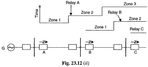
Zone 1: Fast and Definitive
- Reach: Set to 80% of the protected line's impedance.
- Speed: Instantaneous (no intentional time delay, typically operating in less than 40 milliseconds).
By deliberately setting Zone 1 to "under-reach" the end of the line, we create a definitive, high-confidence zone. If the relay measures an impedance within this 80% range, it knows the fault is definitely on its protected line and can trip the circuit breaker immediately without any risk of tripping for faults on other lines.
Zone 2: Covering the Rest of the Line
This leaves the last 20% of the line unprotected by the instantaneous Zone 1. To cover this, we add a second zone.
- Reach: Set to 120% of the protected line's impedance.
- Speed: Time-delayed (typically 0.3 - 0.6 seconds).
Zone 2 over-reaches the protected line and covers the first part of the next line section. The time delay is crucial for coordination. If a fault occurs on the next line, its own Zone 1 protection will trip instantaneously. Our Zone 2 relay will see the fault, start its timer, but the fault will be cleared by the other relay before our timer expires.
If, however, the fault is in the last 20% of our line (the "end-zone"), the other line's protection won't see it. Our Zone 2 timer will run to completion, and our relay will trip the breaker. This ensures 100% of our line is protected, albeit with a short delay for faults at the far end.
This text from Roadnight Taylor provides a concise summary of this two-zone principle.
What is network protection and what risk can it bring ...
The article 'What is network protection...' provides a very clear and simple explanation of the core concept of distance protection, focusing on the roles of Zone 1 and Zone 2.
Please read the short section titled '2. Distance protection'. It perfectly summarises the logic behind the 80% (Zone 1) and 120% (Zone 2) settings.
Zone 3: Remote Backup
Often, a third zone is added to provide backup protection for the entire adjacent line section.
- Reach: Set to cover 100% of the protected line plus 100% of the longest adjacent line.
- Speed: Longer time-delay (typically 1.2 - 1.5 seconds).
If the primary protection on the adjacent line (and its Zone 2 backup from our relay) completely fails to operate, Zone 3 will eventually trip after its long delay. This acts as a final safety net to clear a persistent fault that other systems have failed to address.
Visualizing the Zones
Protection engineers visualize these zones on an R-X diagram, which plots resistance (R) on the x-axis and reactance (X) on the y-axis. The line being protected is a vector on this diagram, and each protection zone is represented by a shape (often a circle) enclosing the area of operation.
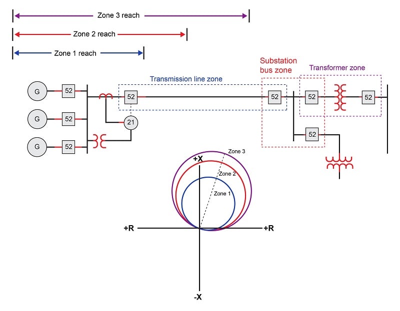
The following video provides a detailed walkthrough of a multi-section power line, showing exactly how the three zones of each relay are set and how they coordinate with each other.
Lecture 14 Protection of Transmission Lines Using Distance Relays-I
Now let's dive deeper with the lecture 'Protection of Transmission Lines Using Distance Relays' from IIT Roorkee. This video provides a comprehensive explanation of the three-zone stepped distance philosophy.
Watch the segment from 14:43 to 23:58. This is the core of the lesson. Pay close attention to how the reach and time delays of Zone 1, Zone 2, and Zone 3 are defined to provide both primary and backup protection.
Test your understanding!
Imagine two transmission lines connected in series: Line AB and Line BC.Substation A --- (Relay A) --- Line AB --- (Relay B) --- Substation B --- (Relay C) --- Line BC --- Substation C
A fault occurs on Line BC, very close to Substation B.
- Which relay's Zone 1 should operate to clear this fault?
- Which relay's Zone 2 will see the fault and start its timer, but should not complete its operation?
Show answer
-
Relay C's Zone 1 should operate. Relay C is located at Substation B looking towards C. The fault is at the beginning of its protected line (Line BC), so it falls squarely within its instantaneous 80% reach.
-
Relay A's Zone 2 will see the fault. Relay A is at Substation A looking towards B. Its Zone 2 setting is 120% of Line AB's impedance, so it over-reaches Substation B and sees the fault at the start of Line BC. It will start its ~0.4-second timer. However, Relay C's Zone 1 will trip instantaneously, clearing the fault long before Relay A's Zone 2 timer expires. This is a perfect example of correct coordination.
Conclusion
In this lesson, we've moved beyond simple overcurrent protection to understand the more advanced method used for our critical transmission infrastructure. Distance protection provides the speed and selectivity needed to keep the high-voltage grid secure.
Key Takeaways:
- Distance protection works by measuring impedance (), which is proportional to the distance to a fault.
- It is the primary protection method for transmission lines because its operation is independent of source impedance and power flow direction.
- A stepped scheme with multiple zones is used to ensure both high-speed tripping and security against incorrect operation.
- Zone 1 provides instantaneous tripping for faults on the majority (~80%) of the line.
- Zone 2 is time-delayed and over-reaches (~120%) to protect the remaining ends of the line.
- Zone 3 has a longer time delay and provides remote backup for adjacent lines.
In the next lesson, we will examine another fundamental protection principle. While distance protection is perfect for long lines, it isn't suitable for compact but critical assets like generators, transformers, or substation busbars. For these, we will explain the principle of differential protection, a highly selective method that works by comparing the current entering an asset to the current leaving it.