Hello! Welcome back to your course on the UK electrical grid.
In our last lesson, we established a crucial principle: transmitting electricity at very high voltages is essential to minimise power losses ($P_{loss} = I^2R$). We saw how stepping up the voltage drastically reduces the current, making the grid efficient over long distances.
This naturally leads to the question: where and how does this voltage change happen? The answer lies in the substations you see across the country. This lesson will explore their role, addressing the learning outcome:
Explain the functions of transmission substations, including voltage transformation and power routing.
We will cover the two primary jobs of a transmission substation: changing voltage levels and directing the flow of electricity, much like a major junction on the motorway system.
1. The Core Functions of a Substation
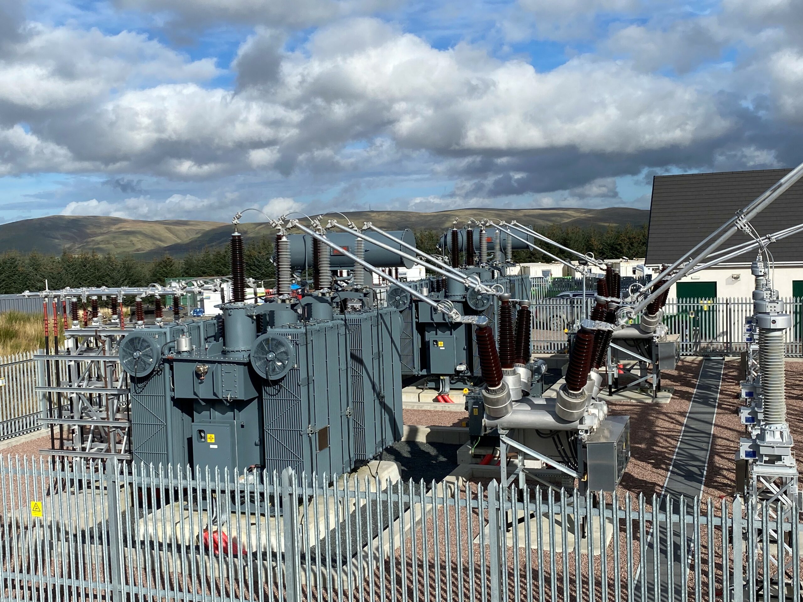
At its heart, a substation is a connection point in the grid. It links power generation sources, transmission lines that move power across the country, and the distribution networks that deliver it to our communities.
To manage this, substations perform two main functions:
- Voltage Transformation: Changing the voltage up or down.
- Power Routing: Controlling the path that electricity takes through the network.
Let's start with the function that directly follows our last lesson.
2. Function 1: Voltage Transformation
As we learned, power is generated at a relatively low voltage (e.g., 25 kV), stepped up to a very high voltage (e.g., 400 kV) for transmission, and then stepped back down for local use. Substations are where this "stepping" happens, using large devices called transformers.
The following video explains the fundamental principle of how a transformer works.
This segment from the 'How Do Substations Work?' video by Practical Engineering provides a clear, simple explanation of a transformer's operation.
Watch the section from 06:47 to 08:24. Focus on how the ratio of coils in a transformer allows it to either increase (step up) or decrease (step down) the voltage.
As the video showed, a transformer uses two coils of wire and a magnetic field to change the voltage. The key is the turns ratio:
- If the second coil has more turns than the first, the voltage is stepped up.
- If the second coil has fewer turns than the first, the voltage is stepped down.
This simple but powerful principle is applied at different points in the grid. The next video puts this into the context of the UK system.
This clip from 'How the UK Grid Works' by The Electric Brit follows the journey of power from a power station to the distribution network.
Watch the segment from 20:11 to 21:58. Note the two key stages where transformers are used: first to step up the voltage for transmission, and then to step it down for distribution.
To summarise the journey:
- Generation Substation: Electricity is produced at a power station (e.g., at 25 kV). A transformer at or near the power station steps the voltage up to transmission levels (275 kV or 400 kV).
- Grid Supply Point (GSP) Substation: After travelling across the country on high-voltage lines, the electricity arrives at a transmission substation. Here, a transformer steps the voltage down (e.g., from 400 kV to 132 kV) to hand it over to the local Distribution Network Operator (DNO).

3. Function 2: Power Routing
Besides changing voltage, substations act as critical junctions that control the flow of electricity. This is the power routing or switching function. Think of it as a set of points and signals on a railway, directing trains onto different tracks.
This capability is essential for:
- Reliability: If a transmission line is damaged or needs to be taken out for maintenance, power can be re-routed through other lines to prevent outages.
- Flexibility: Grid operators can change power flows to manage congestion, similar to how navigation apps divert traffic around a jam.
To understand how this works, we need to know three key components.
Substation configuration and build types
This page from National Grid defines the essential equipment used for power routing inside a substation.
Read the definitions for 'Switchgear', 'Circuit breaker', and 'Busbar'. These are the fundamental building blocks for controlling power flow.
In simple terms:
- Busbar: A solid metal bar that acts as a common connection point for multiple circuits, like a big multi-socket extension lead.
- Circuit Breaker: A high-voltage switch that can interrupt the flow of electricity, especially under fault conditions.
- Switchgear: A general term for all the switching equipment, including circuit breakers and other devices (isolators, fuses).
The arrangement of these components determines how flexible and reliable the substation is. The following reading explains two common configurations.
Substation configuration and build types
Continuing with the same National Grid resource, this section describes how different busbar layouts enable different levels of routing flexibility.
Read the two sections titled 'Single busbar' and 'Double busbar'. Compare the two designs, focusing on how the double busbar provides greater flexibility for maintenance and handling faults.
Let's break down the difference:
-
Single Busbar: All incoming and outgoing circuits are connected to one main busbar.
- Advantage: Simple and cheap.
- Disadvantage: A fault on the busbar, or the need to do maintenance on it, requires shutting down the entire substation. There is no alternative path for the power.
-
Double Busbar: There are two busbars (a 'main' and a 'reserve'). Each circuit can be connected to either one.
- Advantage: Highly flexible and reliable. If the main busbar needs maintenance, all circuits can be temporarily moved to the reserve busbar without any interruption.
- Disadvantage: More complex, takes up more space, and is more expensive.
High-importance transmission substations in the UK typically use double busbar or even more complex arrangements to ensure the grid remains secure and reliable.
Conclusion
In this lesson, we've demystified the role of the transmission substation, showing it to be far more than just a collection of electrical equipment.
Key Takeaways:
- Substations have two primary functions: voltage transformation and power routing.
- Transformers are used to step voltage up for efficient long-distance transmission and step it down for safe local distribution.
- Power routing is achieved using a system of busbars, circuit breakers, and other switchgear. This allows operators to control the path of electricity for maintenance, fault management, and grid flexibility.
- The physical layout, such as a single or double busbar configuration, determines a substation's reliability and operational flexibility.
Preview of the Next Lesson
We've now seen that switchgear is essential for power routing. In the next lesson, we will zoom in on these components to understand exactly how they work. We will address the learning outcome: "Explain the function of circuit breakers, isolators, and switchgear in substations."