Welcome back. In our last lesson, we completed our tour of the CHIP-8's virtual CPU by examining its register set. We saw how the V registers handle data, the PC drives execution, and the I register points to locations in memory. Now, we'll turn our attention to a crucial piece of data that lives in that memory: the built-in font set.
This lesson focuses on the hexadecimal sprites (0-F) that are a fundamental part of the CHIP-8 platform. Our goal is to understand what these sprites are, how their visual patterns are encoded into binary data, and where they are traditionally stored within the system's memory map. This knowledge is essential, as CHIP-8 programs rely on these pre-loaded graphics to display numbers and characters.
Sprites as the Basis for Graphics
In early computer graphics, a sprite referred to a two-dimensional bitmap that could be moved around on the screen independently of the background. In the CHIP-8, all graphics are drawn using sprites. This includes game objects, user interface elements, and, most fundamentally, text characters.
The font set consists of 16 characters representing the hexadecimal digits: 0, 1, 2, 3, 4, 5, 6, 7, 8, 9, A, B, C, D, E, F. Each character is a small sprite, just 5 bytes long. Since CHIP-8 sprites are always 8 pixels wide, this means each character is an 8x5 pixel graphic.
Let's begin by looking at the entire font set visually.
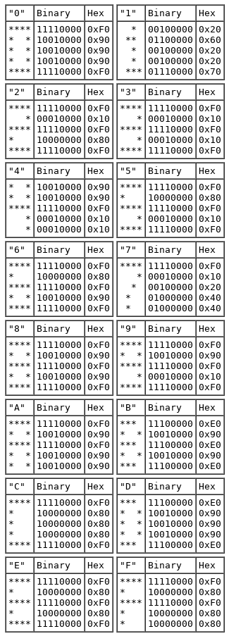
Take a moment to study the image above. For any given character, like "A", you can see how the pattern of asterisks corresponds to the 1s and 0s in the binary column, which in turn are represented by the values in the hex column. Your experience with hardware design and low-level data representation will make this direct mapping between bits and pixels intuitive.
From Pixels to Bytes
The key to understanding CHIP-8 graphics is that each bit in a sprite's byte corresponds to a single pixel: a 1 means the pixel is "on" (lit), and a 0 means it's "off" (dark).
To make this concrete, let's examine how a character is encoded.
Building a CHIP-8 Emulator [C++] - Austin Morlan
This article by Austin Morlan provides a clear, practical explanation of how font sprites are structured.
Please read the section titled Loading the Fonts. It uses the character 'F' as an example to demonstrate the direct relationship between the hexadecimal byte values, their binary representation, and the visual shape of the character.
As the article explains, the five bytes for the character 'F' are 0xF0, 0x80, 0xF0, 0x80, 0x80. Let's break down this representation step-by-step:
| Hex | Binary | Visual |
|---|---|---|
0xF0 |
11110000 |
****.... |
0x80 |
10000000 |
*....... |
0xF0 |
11110000 |
****.... |
0x80 |
10000000 |
*....... |
0x80 |
10000000 |
*....... |
(Dots represent 'off' pixels for clarity)
The entire font set, comprising 16 characters at 5 bytes each, is stored as a single 80-byte block of data. When we build our emulator, we will hardcode this block and load it into the CHIP-8's memory.
Storage in the Interpreter Memory Area
In our first lesson, we learned that the first 512 bytes of memory (addresses 0x000 to 0x1FF) were historically reserved for the CHIP-8 interpreter itself. Since our emulator exists outside this virtual memory space, this area is free for other uses. The font set is loaded into this region.
However, there's a common point of ambiguity among CHIP-8 resources regarding the exact starting address. Some specifications place the fonts at the very beginning of memory, 0x000. A more widespread and robust convention, however, is to place them starting at address 0x050.
Building a CHIP-8 Emulator [C++] - Austin Morlan
Let's refer back to the Austin Morlan article to see this convention stated explicitly.
In the section "4K Bytes of Memory", focus on the bullet points describing the memory segments. The second bullet point clearly identifies the standard location for the font set: Storage space for the 16 built-in characters.
By loading the 80 bytes of font data at 0x050, the fonts occupy the memory range from 0x050 to 0x09F. For our project, we will adhere to this 0x050 starting address, as it is a well-established standard that ensures compatibility with a wide range of CHIP-8 programs.
Accessing Font Data
With the font data loaded into a known memory location, a CHIP-8 program needs a way to find the specific 5-byte sprite for a character it wants to draw. This is accomplished using the I (index) register we discussed in the last lesson, in combination with a dedicated instruction.
The instruction FX29 is designed for this exact purpose. It takes a value from one of the V registers (let's say Vx), which holds a single hex digit (0-15), and sets the I register to the memory address of the corresponding sprite.
The calculation is straightforward:
Let's see this in practice. If we want to draw the digit '8':
- The program would first have the value
8in a register, sayV3. - It would then execute the instruction
F329. - Our emulator would perform the calculation:
0x050 + (8 * 5) = 0x050 + 40 = 0x050 + 0x28 = 0x078. - The
Iregister would be set to0x078.
Now, the I register points to the first of the 5 bytes that define the '8' sprite. The program can then use another instruction (which we'll cover later) to read these 5 bytes from memory starting at address I and draw them to the screen.
Building a CHIP-8 Emulator [C++] - Austin Morlan
The same article describes the FX29 instruction and its implementation, confirming this logic.
Scroll down to the opcode implementations and read the description for Fx29. Notice how the C++ code directly implements the formula we just discussed.
Conclusion
In this lesson, we've unpacked the structure and storage of the CHIP-8's built-in font set. This small but vital component demonstrates key principles of early computer graphics: representing images as binary data and managing that data within a constrained memory space.
Here are the key takeaways:
- The CHIP-8 includes a built-in font set for hexadecimal digits
0throughF. - Each character is an 8x5 pixel sprite, encoded as 5 bytes of data.
- Within each byte, a
1bit represents an "on" pixel and a0bit an "off" pixel. - This 80-byte font set is conventionally loaded into the interpreter's memory area, starting at address
0x050. - The
FX29instruction calculates the address of a specific character sprite and loads it into theIregister, making it available for drawing operations.
We now have a solid understanding of the CHIP-8's memory map, its registers, and its built-in font data. In our next lesson, we will delve into the core of the machine's operation: the instruction format. We will learn how all instructions, including FX29, are encoded as 2-byte opcodes and how the CPU decodes them to understand what action to perform.