In our last lesson, we established the fundamental control logic for a star-delta starter, focusing on the start/stop sequence and the essential electrical interlocks that prevent catastrophic failure. We treated the timer as a "black box" that magically handled the switching. Now, it's time to open that box.
This lesson focuses squarely on the on-delay timer, the component that automates the transition from the star to the delta configuration. You will learn how this specific type of timer works and how to integrate its contacts into the control circuit we previously designed. This will complete the core logic for controlling the 15kW conveyor motor in our project, paving the way for its implementation in EPLAN.
The Role of the On-Delay Timer
The star-delta starting sequence requires a specific pause after the motor starts before switching to the full running configuration. This pause allows the motor to accelerate to about 80-90% of its rated speed while in the star connection, which significantly softens the current surge during the final switch to delta. An on-delay timer is the perfect device for managing this pause.
Its operation is defined by a "delay on energization":
- When power is applied to the timer's coil, its internal clock begins to count down from a preset time.
- Crucially, its contacts—both Normally Open (NO) and Normally Closed (NC)—remain in their normal, unpowered state during this countdown.
- Once the time elapses, the contacts change state: the NO contact closes, and the NC contact opens.
- The contacts will hold this new state for as long as the coil remains energized.
- When power is removed from the coil, the contacts instantly snap back to their normal state.
This behavior allows us to create a precise, automated sequence: use the initial state to run the star contactor, and the timed (delayed) state to run the delta contactor.
Integrating the Timer into the Control Circuit
Let's modify our control circuit to include the timer. The diagram below shows a standard implementation. Here, K1 is the main contactor, K2 is the delta contactor, K3 is the star contactor, and K1T is the on-delay timer.
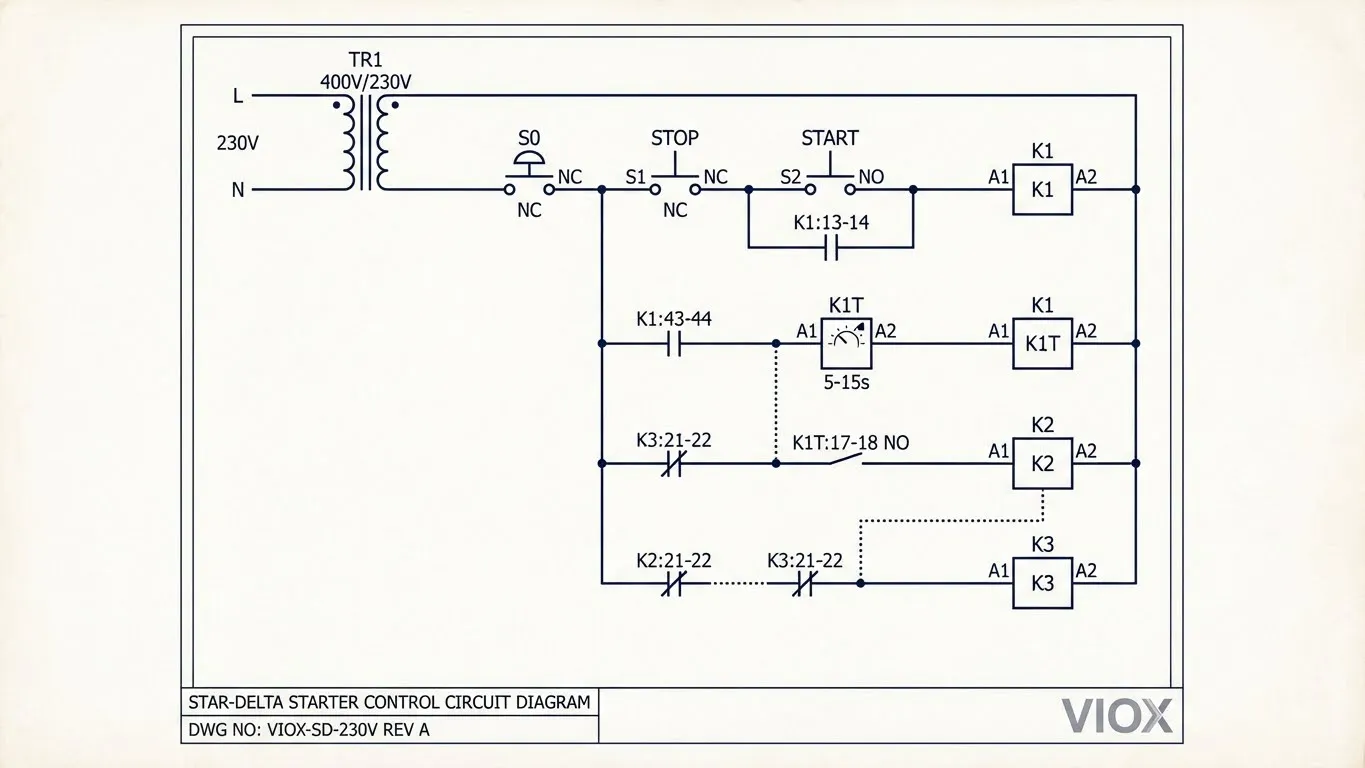
Let's trace the flow of this automated circuit:
-
START & Latch: When the
STARTbutton (S2) is pressed, current flows to the main contactor coil (K1) and, in parallel, to the on-delay timer coil (K1T). The main contactor's auxiliary contactK1:13-14closes, latching the circuit. At this moment, bothK1andK1Tare energized, and the timer starts its countdown. -
Star Connection (t=0): Since the timer has just been energized, its timed contacts are still in their normal state. Current flows through the timer's Normally Closed (NC) contact
K1T:17-18(note: the diagram labels it NO, which is a common but confusing convention; it's a timed NO contact that is initially closed, or more simply, a timer's NC contact). This current then flows through the delta contactor's NC interlock (K2:21-22) and energizes the star contactor coil (K3). The motor is now running with the main and star contactors engaged. -
Delta Connection (t > delay): After the preset time (e.g., 10 seconds), the timer's contacts "time out" and switch state.
- The NC contact (
K1T:17-18) opens, cutting power to the star contactor coil (K3). The star contactor de-energizes. - Simultaneously, the timer's Normally Open (NO) contact (not explicitly shown in this simplified diagram, but its action is what drives the next step) closes. In the diagram shown, this is represented by the logic path opening for K3 and closing for K2. A more explicit diagram would show current flowing through the timer's timed NO contact, then through the star contactor's NC interlock (
K3:21-22), energizing the delta contactor coil (K2).
- The NC contact (
The motor is now running in its final delta configuration, with the main (K1) and delta (K2) contactors engaged. The entire sequence happened automatically after a single press of the START button.
To see this wiring performed with physical components, the following video provides a clear, practical demonstration.
Star Delta Starter Control Wiring Explained Practically @TheElectricalGuy
This video from "The Electrical Guy" shows the step-by-step wiring of a star-delta starter, focusing on how the timer is physically integrated.
First, watch the segment showing the timer being added to the circuit. Then, see how the timer's NC contact is used to wire the star contactor. Next, observe the wiring of the delta contactor using the timer's NO contact. Finally, watch the full demonstration to see the complete automated sequence.
Setting the Timer: An Engineering Decision
The timer's delay isn't arbitrary. It's a key engineering parameter.
- Too short: If the switch to delta happens too early, the motor won't have reached sufficient speed. The result is a high current spike, similar to a DOL start, defeating the purpose of the starter.
- Too long: If the motor runs in the star connection for too long, it can overheat, as it's not designed for continuous operation with reduced voltage. It's also inefficient.
The goal is to set the timer just long enough for the motor to reach about 80-90% of its rated speed. For our project's 15kW (~20 HP) motor, a typical setting would be between 7 and 12 seconds, depending on the conveyor's load. The following guide provides excellent practical advice on determining the right setting.
Star Delta Starter Guide: Wiring, Timer Settings & Motor Control
This article from Electrical World gives a practical breakdown of how to choose and fine-tune timer settings.
Start by reading the section Timer Settings and Calculations. Pay close attention to the table "Practical Timer Settings by Motor Size". Then, review the troubleshooting sections for "Timer Set Too Short" and "Timer Set Too Long". This will solidify your understanding of the consequences of an incorrect setting.
The Complete Control Logic
By adding the on-delay timer, we've finalized the control logic for our 15kW conveyor motor. This logic, which you will soon be implementing in EPLAN, combines the latching circuit, safety interlocks, and automated sequencing.
The video below offers one more clear, animated explanation of the entire control circuit, reinforcing how all the components work together.
star delta control wiring diagram with timer explained by @TheElectricalGuy
This animated diagram from "The Electrical Guy" provides a final, comprehensive walkthrough of the complete star-delta control circuit with a timer.
Watch the segments that explain the timer connection, the use of its NC and NO contacts, the need for interlocking, and finally, the complete working principle.
Conclusion
In this lesson, you've moved beyond the basic interlocking of a star-delta starter and have now mastered the method for automating its operation. By incorporating an on-delay timer, the circuit now correctly sequences the contactors with a single command from the operator.
Key Takeaways:
- An on-delay timer provides a time delay after its coil is energized before its contacts change state.
- In a star-delta starter, the timer coil is energized simultaneously with the main contactor.
- The timer's NC contact controls the star contactor, allowing it to run during the initial countdown.
- The timer's NO contact controls the delta contactor, energizing it only after the time delay has elapsed.
- The timer setting is a critical parameter based on the motor's acceleration time under load.
Our control circuits for both the DOL and star-delta starters are now functionally complete. The next and final step in our theory module is to add visual feedback for the operator. In the next lesson, we will specify and wire the fault and status indication lamps that report what the circuit is doing.