Hello! In our last session, we drew the power circuit for the 3 kW exhaust fan motor using a Direct-On-Line (DOL) starter. This was a great first step, establishing the fundamental flow of power from the supply to the motor through protective and switching devices.
Today, we level up. Your project's 15 kW conveyor motor is significantly larger, and a simple DOL start is no longer appropriate. We need a more sophisticated method to manage the powerful electrical forces at play. This lesson will guide you through drawing the power circuit for a Star-Delta starter, the industry-standard solution for medium-sized motors like the one in your project. We'll explore why it's necessary and how it's constructed.
The Problem with Big Motors: Inrush Current
When a large three-phase induction motor starts, it behaves momentarily like a transformer with a short-circuited secondary. This causes it to draw a massive amount of current from the supply, known as inrush current. This current can be 5 to 8 times the motor's normal full-load running current.
For your 15 kW motor, this could mean a temporary spike of over 150 amps. Such a large, sudden demand can cause:
- Voltage Dips: The lights in the factory might dim, and more sensitive electronic equipment could malfunction or reset.
- Mechanical Stress: The abrupt application of full torque can jolt the conveyor belt and its drivetrain, causing premature wear and tear.
- Electrical Stress: It puts a heavy strain on cables, circuit breakers, and other components in the electrical panel.
The solution is to start the motor with a reduced voltage to limit this inrush current. This is precisely what a Star-Delta starter does.
The Theory: Star (Y) vs. Delta (Δ) Connection
A standard three-phase motor suitable for Star-Delta starting has its three internal windings brought out to six separate terminals in its terminal box (U1/U2, V1/V2, W1/W2). This allows us to connect the windings in two different configurations.
The following video provides an excellent visual explanation of these two configurations and why we need them.
Star Delta Starter Explained - Working Principle
This video from "The Engineering Mindset" is one of the clearest explanations available on the Star-Delta principle. It visualizes the motor windings and the current flow.
Please watch these three segments: Why Star-Delta? First, watch from this section to understand the core problem of inrush current and how Star-Delta provides a solution by reducing torque and current. Winding Configurations: Next, watch from this segment. It shows how the six motor terminals correspond to the internal windings and how they can be physically linked to create either a Star (Y) or a Delta (Δ) connection. Voltage & Current: Finally, watch the simplified electrical example from this clip. It walks through the calculations showing that in a Star connection, the voltage across each winding is reduced by a factor of 1/\sqrt{3} (approximately 58%), which consequently reduces the starting current.
As you saw in the video, the key takeaways are:
- Star (Y) Connection: Used for starting. The windings are connected to a common central point. This configuration subjects the windings to a lower voltage (), resulting in roughly 1/3 of the starting current and 1/3 of the starting torque compared to a direct start.
- Delta (Δ) Connection: Used for normal running. The windings are connected end-to-end in a loop. This configuration applies the full line voltage across each winding, delivering 100% of the motor's rated power and torque.
The starter's job is to automatically switch the motor from the Star configuration to the Delta configuration after it has reached about 85-90% of its normal operating speed.
The Components of a Star-Delta Power Circuit
To achieve this automatic switching, we need more than just one contactor. The power circuit of a Star-Delta starter uses three:
- Main Contactor (let's call it -K1M): This connects the power supply to the primary side of the motor windings (U1, V1, W1). It remains closed whenever the motor is running.
- Star Contactor (-K2M): Its job is to create the 'star point'. When it closes, it shorts the secondary side of the motor windings (U2, V2, W2) together. It is only active for the first few seconds during startup.
- Delta Contactor (-K3M): This contactor connects the secondary side of the windings back to the primary side in the correct sequence (e.g., W2 to U1, U2 to V1, V2 to W1) to form the delta loop. It closes only after the star contactor has opened.
Additionally, you still need your main MPCB for protection and a Thermal Overload Relay to protect the motor from sustained overcurrents during operation.
Assembling the Star-Delta Power Circuit Diagram
Now, let's put these components together into a schematic. The goal is to wire the three contactors so they can reconfigure the six motor terminals on the fly.
This diagram is the blueprint.

Let's trace the power flow in this diagram:
- Power comes from the supply (L1, L2, L3) through the main protective device (Q1, your MPCB).
- It flows through the Main Contactor (-K1M in our project, labeled "Main Contactor" in the image) to the first set of motor terminals (U1, V1, W1).
- From the second set of motor terminals (U2, V2, W2), the wiring branches to both the Star and Delta contactors.
- The Star Contactor (-K2M, "Star Contactor") has its output terminals linked together. When it closes, it creates the common star point.
- The Delta Contactor (-K3M, "Delta Contactor") takes the connections from U2, V2, W2 and routes them back to the input side of the main contactor, but phase-shifted, to complete the delta loop.
To see this in action, let's watch one final, brief animation.
Star Delta Starter Explained - Working Principle
Let's return to "The Engineering Mindset" video to see an animation of how these three contactors work together to perform the switch.
Watch the segment from this timestamp. It clearly demonstrates the sequence: first, the Main and Star contactors close. Then, the Star contactor opens, and the Delta contactor closes. Pay close attention to the path the electricity takes in each configuration.
A Note on Component Sizing
A key piece of practical engineering knowledge is that the contactors in a star-delta starter are not all sized equally. The following resource provides a table that is invaluable for component selection.
The Ultimate Guide to Star-Delta Starters: Wiring Diagram, Sizing, and Component Selection
This guide from Viox provides excellent, practical information on component selection and sizing.
First, review the Component Breakdown table. This clearly lists the six essential components and their functions. Then, refer to the sizing table in the section Real-World Calculations. Find the row for your 15kW motor and note the recommended AC3 ratings for the contactors.
You should have noticed two important things:
- For your 15kW motor, the recommended contactor for the Main (K1) and Delta (K3) roles is a 32A (AC3) model.
- The Star contactor (K2) can be smaller, rated at 20A (AC3). This is because it only carries the reduced star current for a very short period and is never active at the same time as the Delta contactor. This is a common and safe cost-saving strategy in panel design.
Preview in EPLAN
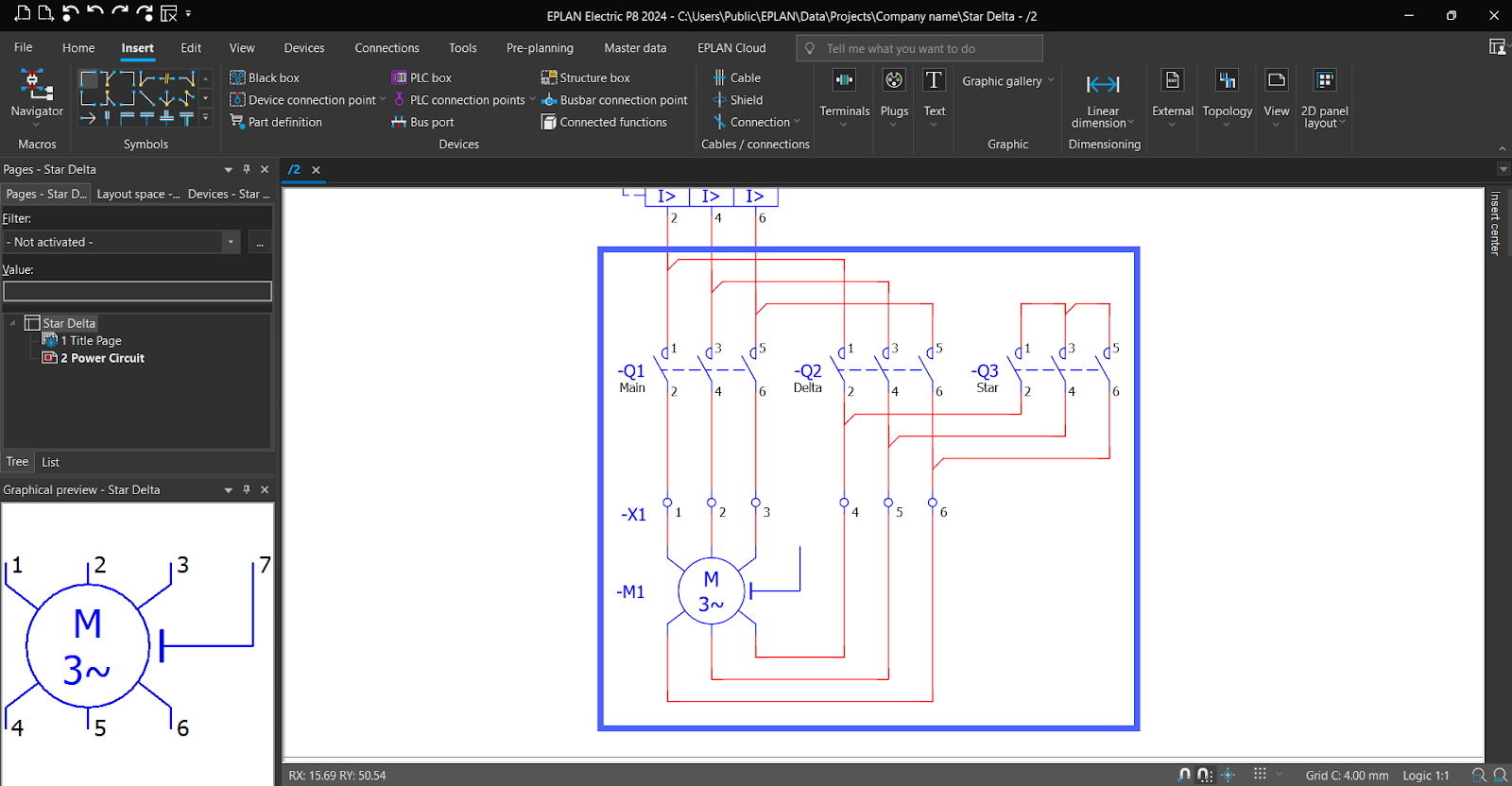
Ultimately, we will draw this circuit in EPLAN. The principles are the same as with the DOL starter: you will place symbols for the MPCB, the three contactors, the overload, and the motor, and then connect them logically. Here is what a finished Star-Delta power circuit looks like inside the EPLAN software. This is the drawing you will create in a later module.
Conclusion
You have now dissected one of the most common motor starting methods used in industry. By understanding the theory and the circuit diagram, you are well-equipped to design and implement it in your project.
Key Takeaways:
- Star-Delta starting is a reduced-voltage method used to limit the high inrush current of larger motors.
- It requires a motor with six terminals and operates in two stages: a low-current Star (Y) connection for starting, and a full-power Delta (Δ) connection for running.
- The power circuit requires three contactors: Main, Star, and Delta, which are wired to reconfigure the motor terminals.
- The typical wiring sequence is: Supply -> MPCB -> Main Contactor -> Motor Terminals (U1,V1,W1). The second set of motor terminals (U2,V2,W2) is then connected to both the Star and Delta contactors to facilitate switching.
In the previous lesson, you drew a simple DOL power circuit. Today, you've diagrammed the much more complex Star-Delta power circuit. You're now familiar with the power schematics for both motors in your project. The next logical question is: how do we control these circuits? In our next lesson, we will begin to answer that by drawing our first control circuit: a latching start/stop circuit which forms the fundamental logic for operator control.