Hello! Welcome to your first lesson on designing an industrial motor control panel.
Your goal is to build a complete EPLAN project for a conveyor and exhaust fan system in a food processing factory. Before we can jump into the EPLAN software, it's crucial to first build a solid understanding of the physical components we will be digitally representing. Just like an architect must know the properties of bricks and steel before designing a building, we need to know what goes inside a control panel and why.
Today’s lesson focuses on exactly that. We will identify the fundamental components of a low-voltage motor control panel and explain the specific role each one plays in making the system work safely and reliably. This will provide the foundational knowledge you'll need for the entire project.
What is a Motor Control Panel?
At its core, the project you are building is a type of Motor Control Center (MCC). An MCC is a centralized enclosure designed to control, protect, and monitor multiple electric motors from a single location. Your panel, which will house the controls for two motors, is a smaller, self-contained version of this industrial concept.
For a formal introduction to the purpose and components of MCC panels, please review the following text.
MCC Panel Guide: Components, Types & Specifications
This guide from Schneider Electric, a major manufacturer of these components, provides a clear and concise overview of what an MCC panel is and what's inside.
Please read the introductory section "What is a MCC Panel?" to get a high-level definition. Then, focus on the section "MCC Panel Components". Read the descriptions for the Main Circuit Breaker, the Electrical Contactor, the Overload Relay, and Busbars. Pay attention to the function of each part.
Now, let's break down these components and a few others in the logical order that power flows through the panel.
The Anatomy of a Motor Control Panel
Imagine electrical power flowing from the building's main supply, into your panel, and finally out to the motors. The components inside are arranged to manage and direct this flow safely.
1. Incomer (Main Isolator)
The first component the power encounters is the incomer, also known as the main isolator or main disconnect switch.
- Function: Its primary job is to provide a means of completely disconnecting the entire control panel from the main power supply. This is essential for safety during maintenance, allowing an engineer to de-energize the cabinet and work on it without risk of electric shock. It often includes a handle on the outside of the panel door that is interlocked, preventing the door from being opened while the panel is energized.
The following video provides an excellent visual of a main isolator and other key components.
Top 8 Electrical Control Panel Components
In this video, Chris Guyatt walks through a real control panel, pointing out the main components. We'll return to this video later, but for now, focus on the first component he discusses.
Watch the segment on the main isolator from this timestamp. Notice how it serves as the entry point for the main power feed.
2. Busbars and Power Distribution
Once inside the panel, the main power feed needs to be split to supply the different circuits (in our case, one for the 15kW motor and one for the 3kW motor).
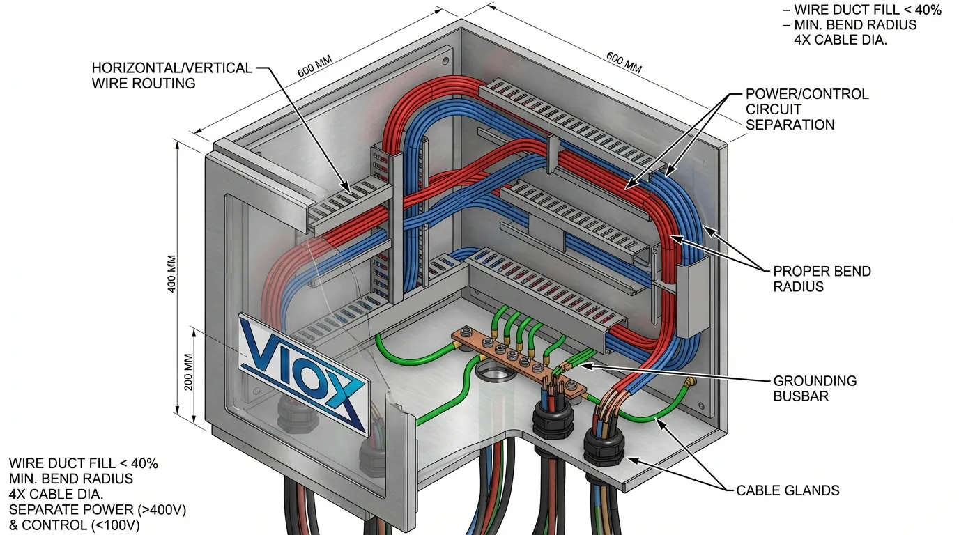
- Function: Busbars are solid copper or aluminum bars that distribute power to multiple circuits within the panel. For smaller panels like ours, it's also common to use power distribution blocks, which serve the same purpose on a smaller scale. They provide a common, secure connection point, ensuring a tidy and efficient distribution of high current.
3. Protection and Switching: The Motor Starter
The "motor starter" isn't a single component, but rather a combination of devices that work together to safely start, stop, and protect a motor. It typically consists of a protective device and a switching device.
Protection Devices (MPCBs, MCCBs, and Overload Relays)
Motors need to be protected from two main types of electrical faults:
- Short circuits: A sudden, very high surge of current, often caused by a wiring fault. This can cause catastrophic damage almost instantly.
- Overloads: A condition where the motor draws more current than it's designed for over a period of time, usually because it's mechanically jammed or overloaded. This causes the motor to overheat and can burn out its windings.
To handle these, we use specialized circuit breakers and relays.

- Motor Protection Circuit Breaker (MPCB): This is an all-in-one device specifically designed for motors. It provides protection against both short circuits and overloads. The overload protection is adjustable, allowing you to set it precisely to the motor's full-load current rating.
- Moulded Case Circuit Breaker (MCCB): A more general-purpose circuit breaker used for higher currents. It provides short-circuit protection and often adjustable overload protection. In a motor circuit, it would be the primary short-circuit protection device.
- Thermal Overload Relay: This device provides only overload protection. It continuously monitors the current drawn by the motor and will "trip" if the current exceeds a set level for too long. Crucially, it does not interrupt the main power circuit itself. Instead, it opens a small auxiliary contact in the control circuit, which in turn tells the contactor to switch off. It must always be paired with a separate device (like an MCCB or fuses) for short-circuit protection.
This distinction between an MPCB (all-in-one) and the combination of a circuit breaker + overload relay is fundamental. The video below explains this difference very clearly.
WHAT IS THE DIFFERENCE BETWEEN THE MOTOR CIRCUIT BREAKER AND THE THERMAL OVERLOAD RELAY?
This video directly compares the functionality of a motor circuit breaker and a thermal overload relay.
Watch the following segments: The introduction explains the core difference: an MPCB combines short-circuit and overload protection, while a thermal relay only handles overload. This part explains the built-in auxiliary contacts on a thermal overload relay (95-96, 97-98), which are vital for the control circuit. This section shows how an overload relay works indirectly by tripping the contactor coil, rather than opening the main power contacts itself. Finally, watch this part to understand that an MPCB needs an additional auxiliary contact block to perform a similar function in the control circuit.
Switching Device (Contactor)
While the circuit breaker is for protection, the contactor is for operation.
- Function: A contactor is a large, heavy-duty, electrically operated switch. A small voltage applied to its internal coil creates a magnetic field that closes a set of large contacts, completing the main power circuit to the motor. When the coil is de-energized, the contacts spring open, stopping the motor. This allows a low-power control circuit (e.g., from a start button) to safely control a high-power motor circuit.
Let's go back to the first video to see a contactor paired with an overload relay.
Top 8 Electrical Control Panel Components
This is the same "Top 8 Components" video from before.
Watch the segment on contactors and overload relays from this timestamp. You can see how the overload relay is physically mounted directly onto the output of the contactor, forming a single "motor starter" unit.
4. Terminals
Finally, we need a way to connect all the panel's internal wiring to the external devices in the factory: the motors themselves, and the operator stations with start/stop buttons and indicator lights.
- Function: Terminal blocks are modular, insulated blocks that secure and organize the connection points between the panel's internal wiring and the field wiring. They are typically mounted on a metal rail (called a DIN rail) and provide a clean, reliable, and easy-to-troubleshoot interface between the panel and the rest of the system.
For a final look at terminals, let's refer back to the components video one last time.
Top 8 Electrical Control Panel Components
From the "Top 8 Components" video.
Watch the section on terminal blocks from this timestamp. The presenter highlights how they connect to field equipment and can also be used for internal power distribution.
Summary
You've now taken a complete tour of the essential components in a motor control panel. These are the building blocks you will be working with throughout this project.
Here are the key takeaways:
- Incomer: The main power switch for the entire panel.
- Busbars / Distribution Blocks: Distribute power from the incomer to the individual motor circuits.
- Motor Starter: The combination of a protective device and a switching device.
- Protection (MPCB or Breaker + Overload): Protects against short circuits and/or overloads to prevent motor damage.
- Switching (Contactor): An electrically operated switch that turns the motor on and off based on commands from the control circuit.
- Terminals: The interface for all wiring entering or leaving the panel.
In our next lesson, we will apply this knowledge practically. We will take the specifications for our 3kW exhaust fan motor, calculate its full-load current, and use that information to select an appropriately sized MPCB and contactor from a manufacturer's catalog.