Hello! In our previous lesson, we organized all our calculated runtimes into a complete, automated weekly irrigation schedule. We now have a solid plan defining what gets watered, for how long, and when.
This lesson brings us to one of the final and most important deliverables of your capstone project: producing the construction-ready drawing. We will focus on translating all your design decisions—layouts, component selections, pipe sizes, and zone groupings—into a single, professionally annotated irrigation plan.
This directly addresses the learning outcome: Produce a final, annotated irrigation plan showing all components, pipe sizes, and a legend.
As a landscape architect, you are already an expert at creating plans. This lesson will build on that skill, focusing on the specific conventions, symbols, and annotations unique to irrigation design. By the end, you'll be able to create a drawing that any contractor can use to accurately bid on and install the system you've designed.
1. The Anatomy of an Irrigation Plan
A professional irrigation plan is not just a sketch; it's a layered set of technical instructions overlaid on an accurate site plan. It must be clear, concise, and contain all the information necessary for installation without ambiguity.
The essential elements we will add to our base site plan are:
- Component Locations: The precise placement of every sprinkler, valve, controller, sensor, and the point of connection (POC).
- Piping Network: The complete routing of all main lines and lateral lines that connect these components.
- Critical Annotations: Labels for pipe sizes, zone numbers, and key notes.
- The Legend: A "dictionary" that defines every symbol used on the plan.
To start, let's review the systematic process of creating the drawing, from the initial scaled plan to the final details.
The 'Irrigation System Design' guide from Hunter Industries provides a formal, step-by-step process for creating a plot plan. We'll focus on the sections that detail the drawing and annotation process.
Please read the following sections to understand the foundational steps of creating your plan: Step 2 - Redraw On Graph Paper (page 8): Focus on the importance of transferring your site sketch to a properly scaled drawing. As an architect, this is familiar territory, but it's a good review of the necessary elements to include. What You Need to Know (Summary Checklist) (pages 12-13): Review the checklists under 'Step 1', 'Step 2', 'Step 3', 'Step 4', 'Step 5', and 'Step 6'. This provides an excellent summary of the entire design-to-drawing workflow we've followed throughout the course.
2. Step-by-Step Guide to Creating Your Plan
Let's break down the creation of the final plan into three manageable steps. We'll use our 600 m² villa project as the example throughout.
Step 1: Draw Components and Piping Using Standard Symbols
The language of any technical drawing is its symbols. In irrigation, symbols allow you to represent complex components simply and clearly.
First, let's establish a set of symbols. While there are industry standards, many designers adopt a consistent set for their practice. A legend should always be included to eliminate any guesswork.
Here is an excellent example of a detailed, professional irrigation legend.

Now, using your chosen symbols, you will draw:
- Component Locations: Place symbols for the controller, POC, backflow preventer, valve manifolds, and every sprinkler head or drip line on your scaled site plan.
- Piping Layout:
- Draw the main line (usually a solid, sometimes heavier line) connecting the POC to the backflow preventer and then to all the valve manifolds.
- Draw the lateral lines (usually a dashed or lighter line) connecting the valve for each zone to all the sprinklers or drip emitters within that zone.
The following guide has a simple and effective illustration of this process.
Hunter's 'RESIDENTIAL SPRINKLER SYSTEM' guide offers a clear, visual approach to laying out the system on paper.
Please review the following pages: Page 8, 'Draw Sprinkler Head Locations': Observe how they begin by placing heads at critical points (corners) and then fill in to ensure head-to-head coverage. Note the use of a compass to draw the spray arcs, which is a key step to visually verify coverage. Page 10, 'Valves and Pipes': Look closely at the illustration. Notice how the main line connects the POC to the valve manifolds, and how separate, dashed lateral lines connect each valve to its respective group of sprinklers. This is a perfect example of how to represent the piping hierarchy.
Step 2: Annotate the Plan with Critical Data
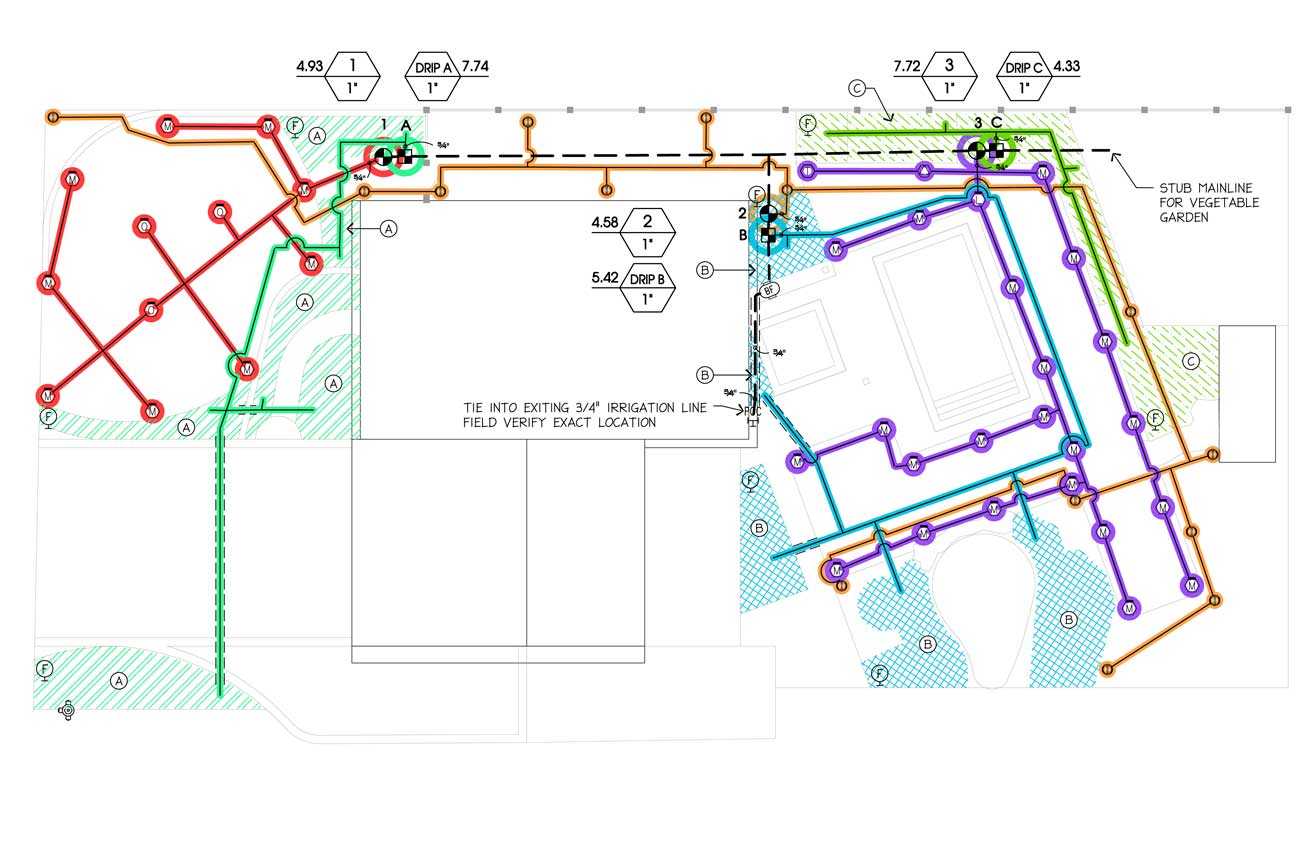
An un-annotated plan is just a picture. The annotations provide the essential data for construction and costing.
Key Annotations to Add:
- Pipe Sizes: For every segment of pipe, label its diameter. For example, you would write
1"orØ32mmnext to a section of the main line, and3/4"orØ25mmnext to a lateral line. This is derived directly from your hydraulic calculations in Module 5. - Zone Identification: Clearly label each zone (e.g., Zone 1, Zone 2...). This is typically done by numbering the solenoid valve that controls the zone.
- Component Specifics: For adjustable sprinklers, you might add a note about the nozzle type (e.g., "MP2000-90").
- General Notes: Every professional plan includes a block of text for general notes. This is where you specify global requirements, such as:
- "All main lines to be Schedule 40 PVC."
- "All lateral lines to be Class 200 PVC or 100 psi Polyethylene."
- "Installation depth for all piping to be 30cm minimum."
- "Contractor to flush all lines before installing sprinkler nozzles."
- "This design is based on a static pressure of 4.5 bar and a flow rate of 4 m³/h at the POC."
This annotated example shows how these elements come together on a final drawing.
Step 3: Create a Comprehensive Legend
The legend ensures anyone can understand your drawing. It must define every symbol you've used. If a symbol is on the plan, it must be in the legend; if it's in the legend, it must be on the plan.
For our villa project, your legend should, at a minimum, include symbols for:
- Point of Connection (POC)
- Backflow Prevention Device
- Automatic Controller
- Solenoid Valve in Valve Box
- Main Line Pipe
- Lateral Line Pipe
- Spray Head (e.g., quarter, half, full)
- Rotor Head (e.g., part-circle)
- Drip Line
Test your understanding!
You have completed your drawing, but the client asks you to add a master valve for extra protection right after the backflow preventer. What two distinct tasks must you complete on your drawing sheet to correctly incorporate this change?
Show answer
- Update the Plan Drawing: You must add the symbol for a master valve in the correct location on the pipe network, between the backflow preventer and the first tee to the zone valve manifolds.
- Update the Legend: You must add the new symbol to your legend with the description "Master Valve" so that the contractor knows what the symbol represents.
From Sketch to Final Drawing
Drafting an irrigation plan is an iterative process. It's helpful to see it being done. The video below provides a practical, over-the-shoulder view of someone sketching out an irrigation design.
Designing Landscape Irrigation | DIYers can do it too!
This video, 'Designing Landscape Irrigation', demonstrates the process of translating a design concept onto paper. Pay attention to how the presenter draws the different components and uses callouts.
Watch the following segments: Sprinkler Layout (9:12 - 11:15): Observe how the designer places the heads, designates their radius ('15 vans'), and draws the arcs to show head-to-head coverage. He also shows how the lateral pipes are routed from the valve assembly. Drip System Layout (16:03 - 17:50): Note how the poly pipe for the drip system is shown snaking through the planter beds to reach all the plants.
Conclusion
You now have the framework to produce the final annotated plan for your capstone project. This drawing is the culmination of all the analysis and calculations you've performed, presented in a format that bridges design and construction.
Key Takeaways:
- A professional irrigation plan is built on an accurate, scaled site plan.
- Use a consistent set of symbols for all components and define them in a legend.
- Clearly differentiate between main lines (pressurized) and lateral lines (zonal) using different line styles.
- Annotate your plan with all critical data, especially pipe diameters and zone identifiers.
- Include general notes to specify materials, installation depths, and design parameters.
In our next and final lesson, we will create the last major deliverable: the Bill of Quantities (BOQ). The annotated plan you've just learned to create will be the primary source document for counting every fitting, every meter of pipe, and every sprinkler head needed for the project.