Welcome to the first lesson of your course on the design of curved steel box girder bridges. Given your extensive experience in bridge engineering with codes like Eurocode, our initial focus will be on establishing a solid foundation in the AASHTO LRFD specification, which will be the framework for our entire design project.
This lesson introduces the core philosophy behind Load and Resistance Factor Design (LRFD). We will explore how this reliability-based approach differs from older methods and unpack the roles of its two most important ingredients: load factors (γ) and resistance factors (φ). Understanding this "why" is the first and most crucial step before we start applying the "how" in subsequent lessons.
1. Design Philosophies: From Allowable Stress to Factored Resistance
Throughout your career, you have undoubtedly encountered various design methodologies. Many older codes were based on Allowable Stress Design (ASD), also known as Working Stress Design. In this approach, the stresses in a structural member, calculated under expected service loads, are kept below a certain allowable stress. This allowable stress is typically the material's yield or ultimate stress divided by a single, comprehensive factor of safety.
AASHTO LRFD, like the Eurocodes you may be familiar with, uses a more refined limit states design philosophy. Instead of one factor of safety, it separates the uncertainties related to loads from those related to material strength and behavior.
To begin, let's watch a video that provides a high-level comparison between these two philosophies.
2-Design philosophies: Load and Resistance Factor Design (LRFD) and Allowable Strength Design (ASD)
This video from the channel Dr. Mohamed Noureldin introduces the three main design philosophies, focusing on Allowable Strength Design (ASD) and Load and Resistance Factor Design (LRFD). It provides the conceptual groundwork for understanding why LRFD was developed.
Please watch the following two segments: The introduction to Allowable Strength Design (ASD), which explains the use of service loads and a single factor of safety. The introduction to Load and Resistance Factor Design (LRFD), which introduces the concept of applying separate factors to loads and resistances.
The key takeaway is the shift in thinking:
- ASD: Required Strength (from service loads) ≤ Allowable Strength ()
- LRFD: Factored Loads (Demand) ≤ Factored Resistance (Capacity)
This separation of factors is the cornerstone of LRFD's reliability-based approach.
2. The LRFD Philosophy: A Reliability-Based Approach
The fundamental goal of the AASHTO LRFD specification is to achieve a uniform and predictable level of safety, or reliability, for all bridges, regardless of their material, span length, or the types of loads they carry. It accomplishes this by statistically accounting for the fact that both loads and resistances are variable and cannot be known with perfect certainty.
- Loads (Q) are uncertain. Traffic loads are highly variable, while the self-weight of the structure (dead load) is more predictable.
- Resistance (R) is also uncertain. Material strength varies from its specified nominal value, fabrication tolerances introduce dimensional variations, and the equations we use to predict strength are themselves approximations.
LRFD explicitly addresses these uncertainties using separate factors for loads and resistances, which are calibrated based on statistical data.
To formalize this, please read a brief section from the AISC publication "Loads and Load Combinations," which discusses the basis of the AASHTO LRFD specifications.
[PDF] Loads and Load Combinations - AISC
This document provides detailed commentary on the load provisions in the AASHTO LRFD specifications. It offers valuable insight into the code's intent.
In the document, please find the section titled "3.1 Reliability-based Design". Read this short section, starting from the main paragraph, to understand how the code aims to achieve a uniform level of reliability.
3. The Fundamental LRFD Equation
This philosophy is captured in a single, fundamental inequality that must be satisfied for all relevant conditions, or "limit states."
The concise video below introduces the different load types and presents the core LRFD equation.
Intro to Structural Analysis - Loads and LRFD
This video by Structures with Prof. H provides a quick and clear overview of structural loads and the LRFD equation.
Watch the full video. Pay close attention to the explanation of factored load combinations and the final presentation of the LRFD equation.
As presented in the video and formalized in AASHTO LRFD Section 1.3.2.1, the basic equation is:
Let's break down each term:
-
Left Side (Demand/Load Effects):
- : The nominal load effect (force, moment, or shear) caused by a specific load type (e.g., dead load DC, live load LL).
- : The load factor applied to load effect . This factor, typically greater than 1.0, accounts for the variability of the load and the probability of multiple loads occurring simultaneously. Loads with higher uncertainty receive larger factors. For instance, the factor for live load (γ_LL = 1.75) is much larger than for steel self-weight (γ_DC = 1.25).
- : A load modifier that relates to ductility, redundancy, and the operational importance of the bridge. We will explore this factor in our next lesson. For most typical designs, it is taken as 1.0.
-
Right Side (Capacity/Resistance):
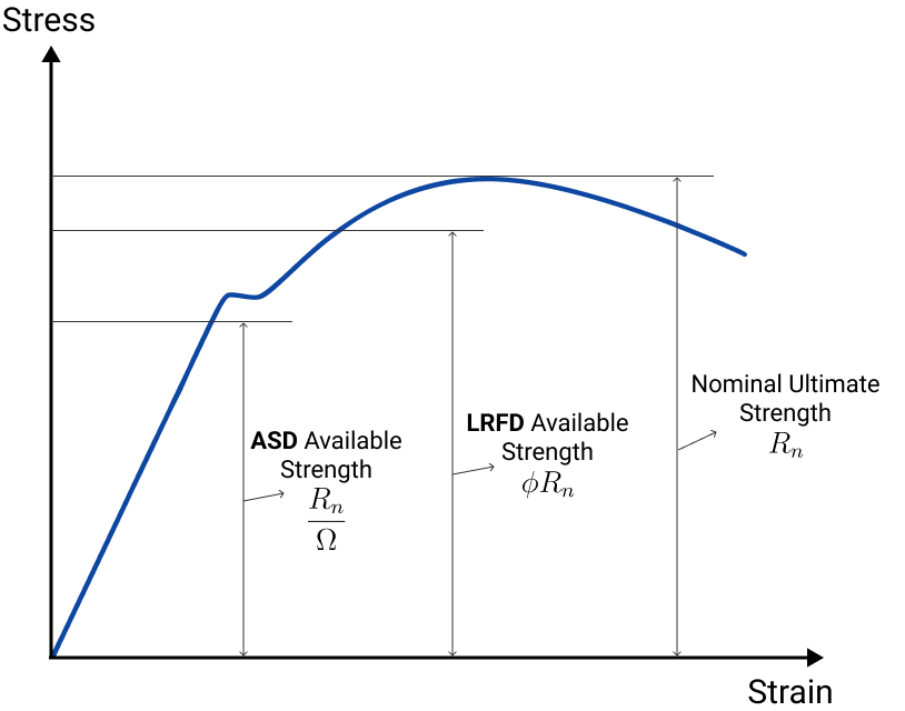
- : The nominal resistance of the component. This is the theoretical, unfactored strength calculated using code equations (e.g., the nominal flexural capacity, ).
- : The resistance factor. This factor, always less than 1.0, accounts for uncertainties in material properties, fabrication tolerances, and the accuracy of the resistance prediction model. The value of depends on the failure mode; ductile and well-understood failure modes (like yielding) receive a higher (e.g., 0.90 or 0.95), while more brittle or less predictable modes (like fracture) receive a lower (e.g., 0.75).
- : The factored resistance, which is the dependable strength of the component that can be relied upon in design.
The following image provides a clear visualization of how the nominal strength, , is reduced to find the available strength in both ASD and LRFD.
4. The Advantages of the LRFD Approach
As an experienced designer, you can appreciate that a design code's philosophy directly impacts engineering practice and project outcomes. LRFD was adopted because it offers several distinct advantages over older methods.
2-Design philosophies: Load and Resistance Factor Design (LRFD) and Allowable Strength Design (ASD)
This final clip from Dr. Noureldin's video explains the practical benefits of LRFD. Though it focuses on building design, the principles are identical for bridges.
Please watch the following segments: A graphical comparison for tension members shows how the economy of LRFD vs. ASD changes with the ratio of live load to dead load, from the graph explanation. The video concludes with a summary of why LRFD should be used, highlighting its rationality, economy, and flexibility.
The primary benefits of LRFD can be summarized as:
- More Uniform Reliability: It provides a more consistent level of safety across different types of structures and materials.
- Improved Rationality: It logically separates uncertainties on the load side from those on the resistance side. This allows the code to be updated more easily as our knowledge of loads (from weigh-in-motion data) or materials (from research) improves.
- Enhanced Economy: For many common structures, particularly those dominated by dead loads (like long-span bridges), LRFD often results in more efficient and economical designs.
- Harmonization: The limit states framework is common across modern codes and materials, making it easier to design structures composed of multiple materials (e.g., steel girders with a concrete deck).
Conclusion
In this lesson, we established the conceptual basis of the AASHTO LRFD specification. You are now equipped with the fundamental principles that will guide every calculation and decision we make in this course.
Key Takeaways:
- LRFD is a reliability-based design philosophy that aims for uniform safety by explicitly accounting for uncertainties in both loads and resistances.
- The fundamental equation is Factored Resistance ≥ Factored Loads ().
- Load factors () are applied to service-level load effects to account for their variability and likelihood of combination. More uncertain loads get higher factors.
- Resistance factors () are applied to the nominal member strength to account for under-performance in materials, dimensions, and strength models. More predictable, ductile failure modes get higher factors.
- This separation of factors allows for a more rational, economical, and flexible design framework compared to older Allowable Stress Design methods.
In our next lesson, we will build directly on this foundation by exploring the different limit states (Strength, Service, Fatigue, and Extreme Event) that AASHTO requires us to check, and we will delve into the application of the load modifier, .