Welcome to the final lesson of our first module on the AASHTO LRFD framework. Over the past several lessons, we've built a solid foundation, moving from the core philosophy of LRFD to the specific details of load combinations, material properties, and, most recently, the stability-driven classification of cross-section elements. We now have a comprehensive understanding of the "demand" side () and the "resistance" side () of the fundamental LRFD equation.
The central goal of any structural analysis is to determine the force effects—the moments, shears, and torsions—that make up the terms in that equation. For the common case of straight, multi-girder bridges, AASHTO provides simplified methods to do this. This lesson's objective is to explain why those simplified methods, specifically live-load distribution factors, are invalid for the curved tub girders we aim to design. Understanding this limitation is not just a procedural detail; it's fundamental to appreciating the unique structural behavior of curved bridges and motivates the need for the refined analysis methods we will study throughout this course.
1. The Simplified Approach: Live Load Distribution Factors (LLDFs)
For decades, the design of standard highway bridges has relied on a powerful simplification. Instead of analyzing the entire bridge as a complex, three-dimensional system of slab and girders, engineers analyze a single girder as a 2D beam. The effect of the 3D system's ability to share load between girders is captured by a Live Load Distribution Factor (LLDF). The moment in a single girder is simply found as:
Here, is the moment from a design lane (or truck) on a simple beam. The LLDF, given as a formula in the AASHTO code, accounts for the girder spacing, span length, and stiffness. This approach works very well for a specific class of bridges.
The AASHTO LRFD Specification explicitly defines the conditions under which these simplified methods are valid. Let's look at the key requirements.
[PDF] section 4: structural analysis and evaluation table of contents
This reading from Section 4 of the AASHTO specification lists the specific geometric and structural prerequisites that must be met to use the simplified live load distribution factors.
In Article 4.6.2.2.1, please review the list of conditions under the heading "Application". Pay close attention to the bullet points that follow, particularly the one regarding plan geometry: "Curvature in plan is less...".
As you've just read, the code itself places a direct limit on curvature for the simplified methods to apply. This begs the question: what is it about curvature that fundamentally changes the structural behavior and invalidates these factors?
2. The Defining Characteristic of Curved Girders: Coupled Bending and Torsion
Your experience is primarily with straight girders, where the response to vertical loads is straightforward: the girder bends and shears in the vertical plane. Torsion is typically a secondary effect, arising only from eccentric loads on the deck or minor construction tolerances. The girders in a straight bridge act largely as independent parallel beams, laterally connected by the deck and cross-frames which mainly provide stability.
A curved girder behaves entirely differently.

When a vertical load is applied to a curved girder, the load path must follow the curvature. This introduces an inherent coupling between bending and torsion. A vertical load causes not only vertical bending but also a significant torsional moment along the girder's length. This torsion is not a secondary effect; it is a primary load effect that must be resisted by the bridge system.
Trapezoidal tub girders are specifically chosen for curved applications precisely because their closed-box shape provides immense torsional stiffness—orders of magnitude greater than an open I-girder section. However, this torsional stiffness also means that the girder will attract significant torsional moments.
Furthermore, these torsional loads can cause the cross-section itself to deform or "distort," which is a phenomenon that leads to additional stresses not accounted for in simple beam theory. The following reading provides an excellent overview of this behavior.
[PDF] Design Guidelines for Steel Trapezoidal Box Girder Systems
This research document explains the fundamental mechanics of box girders, linking their high torsional stiffness to their use in curved bridges and introducing the concept of distortion.
First, read the Introduction to understand why box girders are the preferred choice for curved structures. Next, read the section on Torsional Theory. Focus on the distinction between Saint-Venant torsion (which is what gives the box its stiffness) and the concept of cross-sectional distortion. Finally, jump to Chapter 4 and read the introduction under Controlling Box Girder Distortion. This part explains how torsion leads to distortion and why it can produce significant stresses if not controlled.
The key takeaway is that in a curved bridge, the girders, deck, and bracing do not simply distribute vertical load laterally. They form a complex three-dimensional system that must resist coupled bending and torsion, and control cross-sectional distortion. The very assumptions that allow for the simplification of LLDFs—namely, uncoupled behavior and predictable transverse load sharing—are violated.
3. The Path Forward: Refined Analysis Methods
Since the simplified formulas are inapplicable, AASHTO requires that curved girder bridges be analyzed using a "refined method." This marks a significant shift in design effort, moving from applying a simple formula to building a complete structural model. For you, with your background in FEM, the concept of a refined model is already familiar.
AASHTO recognizes a spectrum of refined analysis methods, each with its own level of complexity and accuracy.
Level 1: Approximate Methods (e.g., M/R or V-Load Method)
As your course preferences indicated a desire to start with manual methods, you will be pleased to know that there are approximate methods developed specifically for curved girders. The most common for box girders is the M/R Method. It treats the curved girder as a straight beam, but adds an equivalent distributed torsional load, , to account for the effect of curvature. This method allows for a manual, 2D analysis to capture the primary coupling of bending and torsion. We will dedicate a full module to applying this method.
Level 2: 2D Grillage Analysis
A more powerful approach is to model the bridge as a 2D grid of frame elements in a computer program. The curved girders are modeled as "spine" members along their curved alignment, and transverse elements are used to model the deck and cross-frames. This method is much faster than a full 3D model and can provide good results for overall force effects (moment, shear, torsion), but it struggles to capture local effects like web bending or cross-section distortion.
Level 3: 3D Finite Element Analysis (FEA)
This is the most accurate and versatile method. The entire superstructure—webs, flanges, deck, and bracing—is modeled using shell or solid elements. This type of analysis directly captures the coupled bending-torsion behavior, cross-section distortion, and the precise load path through all bracing members. Given your experience, this type of model will be conceptually familiar.
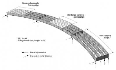
AASHTO commentary specifically acknowledges these methods.
[PDF] section 4: structural analysis and evaluation table of contents
This commentary discusses the approximate analysis methods for curved steel bridges, highlighting their assumptions and limitations, which reinforces the need for more refined analysis in many cases.
Please read Article C4.6.2.2.8 on page 4-21. This commentary discusses the V-load method (for I-girders) and the M/R method (for box girders), noting their limitations and when a more refined analysis is required.
The commentary's cautions are important: even the "simpler" M/R method has limitations, particularly for continuous-span bridges or unusual geometries, often necessitating a more detailed 3D FEA for final design verification.
Conclusion
This lesson serves as the capstone for Module 1 and the launchpad for the rest of our course. We've now established a critical bridge between the general principles of LRFD and the specific, complex world of curved tub girders.
Key Takeaways:
- Simplified LLDFs are for straight bridges: They are based on the assumption of uncoupled bending and predictable transverse load sharing, which is valid for straight, parallel-girder systems.
- Curvature couples bending and torsion: In a curved girder, vertical loads inherently produce primary torsional moments. This is the fundamental difference in behavior.
- AASHTO requires refined analysis: Because the assumptions of LLDFs are violated, AASHTO explicitly limits their use for curved bridges and mandates a refined analysis.
- A hierarchy of refined methods exists: The design of a curved bridge involves a spectrum of analysis techniques, from approximate manual methods (M/R), to 2D grillage models, to comprehensive 3D Finite Element models.
This foundational understanding of why we must use more sophisticated tools is essential. It justifies the detailed analytical work that lies ahead. Having completed our survey of the essential AASHTO LRFD framework, we are now fully prepared to tackle the specifics of our bridge type.
In our next lesson, we will begin Module 2 by focusing on the first step of any analysis: defining the object to be analyzed. We will explore the typical geometry of a steel trapezoidal tub girder, establishing the cross-sectional parameters—web slope, flange widths, and stiffener layouts—that will form the basis of our M/R, grillage, and FEM models.