Hello! Welcome back. It's great to see you again.
In the last module, we became experts in closed systems. We took a fixed amount of gas in a piston-cylinder and put it through all sorts of processes—heating, cooling, expanding, and compressing. We learned how to track the energy meticulously using the First Law, . This was all about analyzing a constant batch of "stuff."
But think about most of the powerful machines that shape our world: a jet engine, a power plant turbine, your car's radiator, or even a simple hairdryer. They don't work with a fixed batch of fluid. Instead, fluid is constantly flowing through them. Air comes into the jet engine, mixes with fuel, burns, and hot gas blasts out the back. Water flows into the radiator, picks up heat, and flows out to be cooled.
These are called open systems, and to analyze them, we need to shift our perspective. We can't just follow a specific chunk of mass anymore because it's always on the move. Today, we're building the foundation for analyzing these dynamic systems. Our goal is to explain and master the core concepts for open systems: the control volume, mass flow rate, and volume flow rate.
Let's start our walk into this new, flowing world.
From Closed Systems to Control Volumes
Up until now, our "system" was always the mass inside a sealed container. The boundary moved, but the mass inside was trapped. That was a closed system.
An open system is one where mass can cross the boundary. To handle this, we stop trying to follow the mass itself and instead define a fixed region in space that we're interested in. This region is called a control volume (CV), and its boundary is called the control surface.
Think of it like being a traffic analyst. You could try to follow one specific car on its entire journey through a city (a closed system approach, following the "mass"). Or, you could stand at one intersection and count all the cars passing through it (an open system approach). You've defined a "control volume"—the intersection—and you're monitoring what crosses its boundaries.
This is exactly what we do in thermodynamics. We draw an imaginary box around a device, like a turbine, and we analyze the mass and energy that cross the boundary of that box.
To get a feel for this, let's look at an analogy and some examples. Imagine a factory.
- The factory building itself is our control volume.
- The walls and doorways are the control surface.
- Raw materials (like iron ore) enter the factory, and finished products (like cars) leave. This is the mass flow.
- Electricity and fuel enter the factory, and heat escapes through the walls. This is the energy flow.
As engineers, we stand at the "doorways" of our control volume and keep track of everything going in and out.
The following video provides a great visual introduction to the idea of a control volume and shows some practical examples.
CONTROL VOLUMES - Closed vs. Open - Extensive vs. Intensive in 9 Minutes!
Please watch the following short clips from the 'Less Boring Lectures' channel. They do a great job of defining the control volume and showing how we apply it to everyday devices.
Please watch the segments from 1:07 to 1:53 and from 6:48 to 8:50. Focus on: The definition of a control volume as a region of interest in space. How to identify the control volume and classify the system (open or closed) for real devices like a water heater or a fridge.
Here are some of the most common devices we'll be analyzing as control volumes. You can see the arrows indicating where the fluid (mass) enters and exits.

Quantifying the Flow: Mass and Volume Flow Rate
Okay, so we've established that mass is flowing through our control volume. The next logical question is: how fast?
Just saying "fast" isn't enough for an engineer. We need numbers. We quantify flow in two main ways: by how much volume is flowing, and by how much mass is flowing.
Volume Flow Rate ()
Volume flow rate is the volume of fluid that passes through a cross-section per unit of time.
- Analogy: Imagine you're filling a bucket with a garden hose. If the hose delivers 10 liters of water every minute, the volume flow rate is 10 L/min. It tells you how much space the fluid takes up.
- Units: Cubic meters per second (m³/s), liters per minute (L/min), or gallons per minute (GPM).
- Symbol: We'll use . The dot on top signifies a "rate" or "per unit time". You might also see it written as , but we'll stick with to avoid any confusion with heat.
Mass Flow Rate ()
Mass flow rate is the mass of fluid that passes through a cross-section per unit of time.
- Analogy: For that same hose delivering 10 liters of water per minute, we know that 1 liter of water has a mass of about 1 kg. So, the hose is also delivering 10 kg of water per minute. The mass flow rate is 10 kg/min. It tells you how much stuff is actually moving.
- Units: Kilograms per second (kg/s), pounds per hour (lb/hr).
- Symbol: . Again, the dot means "rate."
To really solidify the difference, let's check out a quick reading.
The following article from Turbines Incorporated gives a very clear, side-by-side comparison of these two concepts.
Please read the first three short sections titled 'What Is Volumetric Flow Rate?', 'What Is Mass Flow Rate?', and 'Volumetric vs. Mass Flow Rate: Key Differences and Similarities'. Pay special attention to the table comparing the two—it's a great summary.
So, which one is more important? For liquids like water, whose density doesn't change much, volume flow rate is often convenient. But for gases, whose volume can change dramatically with pressure and temperature, mass flow rate is almost always more fundamental. Ten kilograms of air is always ten kilograms of air, whether it's compressed into a scuba tank or expanded in a hot air balloon.
The Formulas for Flow Rate
Let's build the formulas for these flow rates from the ground up. It's actually very intuitive.
Imagine a fluid flowing through a pipe with a cross-sectional area at an average velocity .
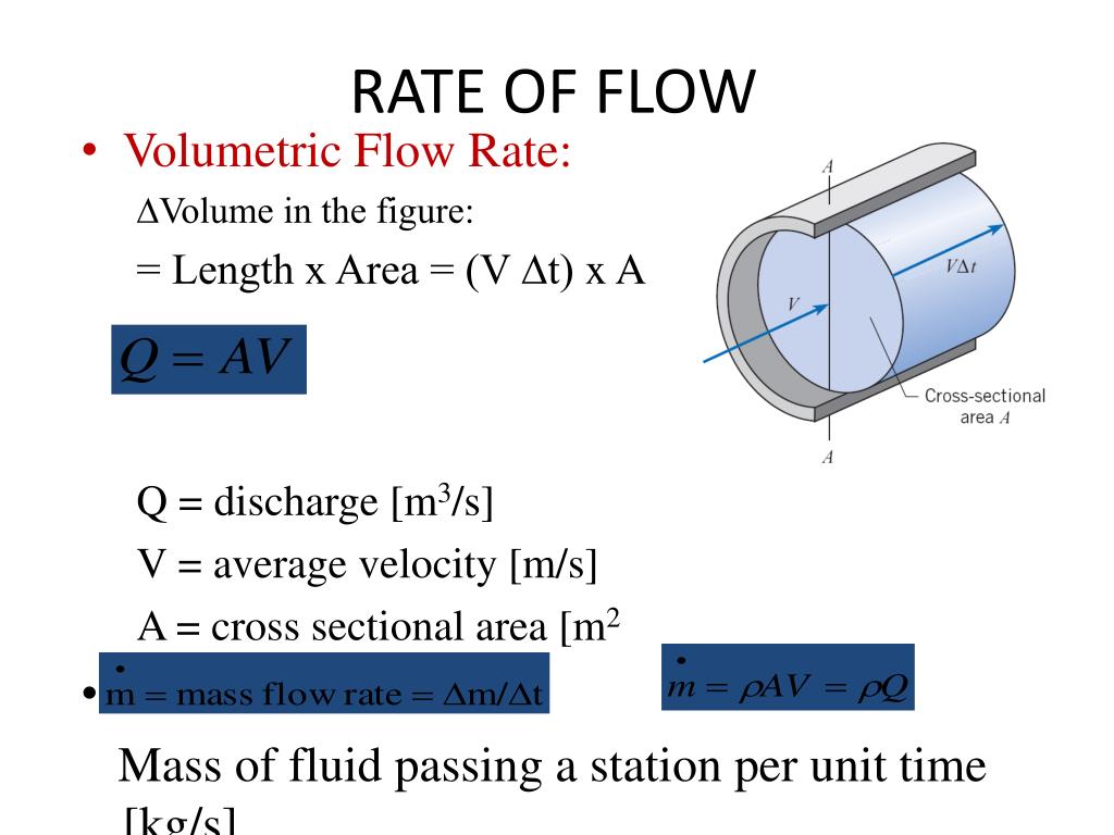
- In one second, a "slug" of fluid will travel a distance of meters.
- The volume of this slug of fluid is its cross-sectional area times its length:
- Since this is the volume that passes by in one second, this is exactly the volume flow rate:
(where is volume flow rate, is area, and is velocity)
Now, how do we get the mass flow rate? We just need to know the density () of the fluid.
Remember the basic relationship: . The same works for rates!
Substituting our expression for , we get the master formula for mass flow rate:
(where is mass flow rate, is density, is area, and is velocity)
Sometimes in thermodynamics, we work with specific volume (), which is just the inverse of density (). So you can also write the formula as:
Let's watch a video that walks through this derivation and the key relationships.
Volumetric and MASS FLOW RATES for Thermodynamics in 8 Minutes!
This video from 'Less Boring Lectures' provides a great mathematical breakdown of these concepts. It clearly connects velocity, area, density, and the two flow rates.
Please watch from 0:54 to 4:21. The key things to focus on are: How multiplying velocity by an infinitesimal area (dA) gives the infinitesimal volumetric flow rate (dV-dot). How multiplying that by density gives the mass flow rate (dm-dot). The final, simplified formulas using average velocity: ṁ = ρAV and ṅ = AV.
Test your understanding!
You have a hose with a nozzle on the end. When you squeeze the nozzle, the opening gets smaller. Assuming you are pumping the same amount of water through the hose (i.e., the mass flow rate is constant), what happens to the velocity of the water coming out of the nozzle? Why?
Show answer
The velocity of the water increases significantly. The reason comes from the mass flow rate equation, . Since water is nearly incompressible, its density is constant. You've also fixed the mass flow rate . This means the product must remain constant. When you squeeze the nozzle, you decrease the area , so the velocity must increase to keep the product the same. This is a direct application of the conservation of mass!
The Law of the Land: Conservation of Mass
That "garden hose effect" is a perfect example of one of the most fundamental rules for control volumes: The Conservation of Mass.
It's simple: mass cannot be created or destroyed. For any control volume, all the mass that flows in must either flow out or accumulate inside.
In this course, we will almost always deal with steady-flow processes. "Steady" means that nothing inside the control volume changes with time. The temperature is constant, the pressure is constant, and—most importantly—the amount of mass inside is constant. This means the accumulation term, , is zero.
For a steady-flow process, the conservation of mass simplifies to:
What comes in, must go out.
For a simple device with one inlet (port 1) and one outlet (port 2), like a pipe or a nozzle, this becomes:
This is the principle we'll use again and again to analyze open systems.
Worked Numerical Problems
Let's put these new formulas to work.
Problem 1: Flow in a Water Pipe
Water ( kg/m³) flows through a pipe with an inner diameter of 2 cm (0.02 m) at an average velocity of 3 m/s. Calculate:
a) The volume flow rate in m³/s.
b) The mass flow rate in kg/s.
Show step-by-step solution
Step 1: Calculate the cross-sectional area (A).
The pipe is circular, so or .
The diameter m, so the radius m.
Step 2: Calculate the volume flow rate ().
The formula is .
So, about 0.942 liters of water flow through the pipe every second.
Step 3: Calculate the mass flow rate ().
The formula is .
So, 0.942 kilograms of water flow through the pipe every second.
Problem 2: Air Flowing Through a Nozzle
Air enters a nozzle at a pressure of 200 kPa and a temperature of 100°C. The inlet area is 80 cm² (which is 0.008 m²), and the air velocity is 10 m/s. The air leaves the nozzle at a point where the area is 40 cm² (0.004 m²) and its velocity is 30 m/s. Assuming steady flow, what is the density of the air at the nozzle exit?
(For air, the gas constant is kJ/kg·K)
Show step-by-step solution
Step 1: State the governing principle.
For steady flow with one inlet (1) and one outlet (2), the conservation of mass states:
We need to find . Let's rearrange the formula to solve for it:
Step 2: Find the density at the inlet ().
We are given pressure and temperature, so we can treat the air as an ideal gas. The ideal gas law is .
First, convert the temperature to Kelvin: K.
The pressure is kPa = 200,000 Pa.
Rearrange for density: .
Note: I used R = 287 J/kg·K to match the units of Pa (N/m²), since 1 J = 1 N·m.
Step 3: Calculate the density at the exit ().
Now we plug all our known values into the rearranged conservation of mass equation.
- kg/m³
- m²
- m/s
- m²
- m/s
The density of the air at the exit is approximately 1.245 kg/m³. This makes sense: as the air sped up and expanded through the nozzle, its density decreased.
Conceptual Questions
- A car's radiator is an open system. What is the "fluid" flowing through it? What is the purpose of this flow? Can you identify the control volume, inlets, and outlets?
- Why is mass flow rate () a more reliable quantity than volume flow rate () when analyzing the combustion process in a car engine?
- You have two pipes. One carries 1 kg/s of water ( kg/m³). The other carries 1 kg/s of air ( kg/m³). Which pipe do you think needs to have a larger diameter to carry the flow at the same velocity? Why?
Show answers
- The "fluid" is the engine coolant (a mixture of water and antifreeze). Its purpose is to absorb excess heat from the engine block and transport it to the radiator to be dissipated into the surrounding air. The control volume would be the radiator itself. The inlet is the hose bringing hot coolant from the engine, and the outlet is the hose returning cooled coolant to the engine.
- In a car engine, both the fuel (liquid) and air (gas) are combined and burned. This combustion process involves massive changes in temperature and pressure. The volume of the gases changes dramatically, but the mass is conserved (the mass of the fuel + air entering equals the mass of the exhaust gases leaving). Basing calculations on mass ensures you're tracking the actual amount of matter involved, which is crucial for chemical reactions and energy balances.
- The pipe carrying the air needs to be much larger. From , we can see that if and are the same for both pipes, then must be the same. Since the density () of air is about 1000 times less than that of water, its area () must be about 1000 times larger to achieve the same mass flow rate. This is why air ducts for ventilation are so much larger than water pipes for the same "amount" of fluid flow in terms of mass.
Conclusion
Fantastic work today. We've taken a significant first step into the world of open systems, which is where most of the heavy-lifting in engineering thermodynamics happens.
Our Key Takeaways:
- We shifted from analyzing closed systems (fixed mass) to open systems (mass can flow across boundaries).
- Our new point of view is the control volume: a fixed region in space where we monitor what comes in and what goes out.
- We learned to quantify flow with volume flow rate (), which measures the space the fluid occupies, and mass flow rate (), which measures the amount of substance.
- We established the fundamental law for steady-flow systems: the conservation of mass, which simply states that the mass flow rate in must equal the mass flow rate out ().
Preview of the Next Lesson
We now know how to account for mass crossing the boundary of our control volume. But what about the energy this moving mass carries with it? A moving fluid has kinetic energy, potential energy, and internal energy, just like we've seen before. But it also carries energy in another, less obvious form, related to the pressure that's pushing it along.
In our next lesson, we will explore this "pushing energy," known as flow work, and combine it with internal energy to define a new, incredibly useful property called enthalpy. This will be the final piece we need to build the full First Law for open systems.