Hello! Welcome to the first lesson of our second module on combinational circuits.
In the previous module, we laid the mathematical groundwork for digital design. You learned how to work with binary numbers, simplify Boolean expressions, and, in our last lesson, derive a Boolean expression directly from a truth table. This is the abstract "language" of digital logic.
Today, we'll bridge the gap between that abstract language and the physical world. We will explore the fundamental building blocks of all digital electronics: logic gates. These are the tiny electronic circuits that actually perform the AND, OR, and NOT operations we've been describing with equations.
Our learning outcome for this lesson is to identify and describe the behavior of basic logic gates (AND, OR, NOT, XOR, etc.). By the end of this 60-minute session, you will be able to recognize the standard symbols for these gates and explain their function using truth tables.
1. What are Logic Gates?
A logic gate is a physical device, typically built from transistors, that implements a Boolean function. It takes one or more binary inputs (representing low and high voltage levels, or '0' and '1') and produces a single binary output. Since your background is in electrical engineering, you can think of these as simple electronic circuits designed to perform a specific logical task.
There are seven basic types of logic gates that form the foundation of virtually all digital systems, from simple calculators to complex microprocessors. Let's start with the three most fundamental ones: NOT, AND, and OR.
Introduction to Logic Gates - NOT, AND, OR, NAND, NOR, XOR, XNOR
Watch this introductory video from the channel Computer Engineering Jitty. It provides a clear, concise explanation of the first three gates.
Pay close attention to these three segments: First, watch the section on the NOT gate. Notice that it has only one input and one output. Next, review the AND gate. Its output is '1' only when all its inputs are '1'. Finally, look at the OR gate. Its output is '1' if any of its inputs is '1'.
2. The Three Fundamental Gates: NOT, AND, OR
The video provided a great overview. Let's formalize what you saw and connect it directly to the Boolean algebra from our previous lessons.
-
NOT Gate (Inverter): This gate inverts its input. A '1' becomes a '0', and a '0' becomes a '1'.
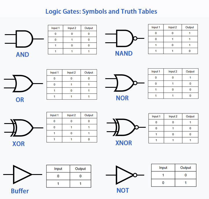
- Symbol: A triangle followed by a small circle (or "bubble"). The bubble signifies inversion.
- Boolean Expression: If the input is , the output is .
-
AND Gate: The output is '1' if and only if all inputs are '1'.
- Symbol: A shape like a capital 'D'.
- Boolean Expression: For inputs and , the output is .
-
OR Gate: The output is '1' if any input is '1'.
- Symbol: A curved shape on the input side.
- Boolean Expression: For inputs and , the output is .
This direct mapping is key: the mathematical operators we used to simplify expressions (¯, ·, +) correspond one-to-one with these physical gates.
3. The Universal Gates: NAND and NOR
Next, we have two gates that are incredibly important in practice: NAND and NOR. Their names are contractions of "NOT AND" and "NOT OR". As their names suggest, their behavior is the exact inverse of the AND and OR gates.
The key feature in their symbols is the bubble at the output, which you now know means inversion.
Introduction to Logic Gates - NOT, AND, OR, NAND, NOR, XOR, XNOR
Let's return to the same video to see how NAND and NOR gates are simply inverted versions of AND and OR.
Watch the explanation of the NAND gate. Notice how its truth table is the exact opposite of the AND gate's. Then, review the NOR gate, which has a truth table that is the inverse of the OR gate's.
-
NAND Gate (NOT AND): The output is '0' only when all inputs are '1'. Otherwise, the output is '1'.
- Boolean Expression:
-
NOR Gate (NOT OR): The output is '1' only when all inputs are '0'. Otherwise, the output is '0'.
- Boolean Expression:
An interesting and powerful property of NAND and NOR gates is that they are universal gates. This means you can construct any other logic gate (AND, OR, NOT, etc.) using only NAND gates or only NOR gates. This is extremely useful in manufacturing, as chip makers can optimize the fabrication process for a single type of gate.
4. The "Difference" and "Equality" Gates: XOR and XNOR
Finally, we have two more specialized gates: Exclusive-OR (XOR) and Exclusive-NOR (XNOR).
- An XOR gate outputs a '1' only if its inputs are different. You can think of it as a "difference detector."
- An XNOR gate does the opposite. It outputs a '1' only if its inputs are the same. This makes it an "equality detector."
Introduction to Logic Gates - NOT, AND, OR, NAND, NOR, XOR, XNOR
One last look at the video will clarify the unique behavior of these gates.
First, watch the segment on the XOR gate. Pay attention to the "exclusively or" logic. Then, finish with the XNOR gate, which is simply the inverted version of the XOR gate.
-
XOR Gate (Exclusive-OR): The output is '1' if an odd number of inputs are '1'.
- Symbol: Like an OR gate, but with an extra curved line on the input side.
- Boolean Expression:
-
XNOR Gate (Exclusive-NOR): The output is '1' if an even number of inputs are '1' (including zero).
- Symbol: An XOR symbol with a bubble at the output.
- Boolean Expression:
5. Summary and a Glimpse of Verilog
You've now seen all the fundamental logic gates. The image below provides a complete summary of their symbols and truth tables, which will be a handy reference as we move forward.
To tie this back to your goal of learning Verilog for the ASIC bootcamp, let's see how these abstract symbols translate into code. Hardware Description Languages (HDLs) like Verilog have operators that correspond directly to these gates.
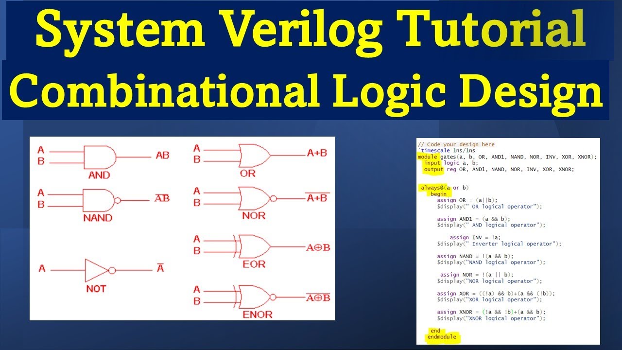
Take a look at the code on the right. You don't need to understand the syntax yet, but notice the operators:
&for AND|for OR~for NOT (inversion)^for XOR
As we progress, you will learn to write Verilog code like this to describe complex circuits built from these simple gates. This is the essence of modern digital design: describing hardware with code.
Conclusion
In this lesson, we transitioned from the abstract world of Boolean algebra to the concrete building blocks of digital circuits.
Here are the key takeaways:
- Logic gates are electronic circuits that implement basic Boolean functions.
- Each gate (AND, OR, NOT, NAND, NOR, XOR, XNOR) is defined by its unique symbol and its behavior, which is captured in a truth table.
- A small circle or "bubble" on a gate symbol represents logical inversion (a NOT operation).
- NAND and NOR gates are known as universal gates because any other logical function can be built from them.
- These theoretical concepts map directly to operators in Hardware Description Languages like Verilog.
You are now equipped to recognize the fundamental components of any digital circuit. In our next lesson, we will take the next logical step: we will start connecting these individual gates to form simple circuits and learn how to analyze their collective behavior.