Hello! Let's continue our journey into heat transfer.
In our last lesson, we established the fundamental principle of heat conduction, Fourier's Law, and applied it to simple, uniform objects. We saw that for a rod in steady state, the heat current is constant and the temperature drops linearly along its length. You learned to calculate this heat current using the formula .
Today, we'll build on that foundation to tackle more realistic and complex scenarios. Our goal is to analyze heat conduction through composite slabs in series and parallel using thermal resistance networks. The key concept we will introduce is thermal resistance. This powerful idea allows us to model heat flow problems using an analogy to electrical circuits, a framework that should be very familiar given your background in CS and mathematics.
1. The Electrical Analogy: Thermal Resistance
Let's start by rearranging Fourier's Law from the last lesson:
Now, compare this to Ohm's Law for electrical circuits:
The similarity is striking. We can establish a direct analogy:
- Heat Current () is analogous to Electric Current ().
- Temperature Difference () is analogous to Potential Difference ().
- Therefore, the term can be defined as Thermal Resistance ().
So, the thermal resistance of a slab of material is given by:
where is the length (thickness), is the thermal conductivity, and is the cross-sectional area.
This analogy isn't just a neat trick; it's a profound problem-solving tool. It means we can use the well-established rules for combining resistors in series and parallel to analyze complex heat flow systems.

To get a formal introduction to this concept, please review the following text.
This article from Curio Physics formally introduces thermal resistance and its relationship to Fourier's Law and Ohm's Law.
Please read the introduction and the section 'Thermal Resistance Formula'. Focus on how the formula for thermal resistance is derived by direct comparison with Ohm's law.
2. Composite Slabs in Series
When slabs are connected in series, they are placed one after another, forming a single path for the heat to flow.
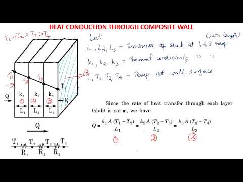
In a series connection, the two key principles are:
- The heat current () is the same through each slab.
- The total temperature difference across the combination is the sum of the temperature differences across each individual slab. ()
From these principles, we can derive the equivalent thermal resistance.
The same Curio Physics article provides a clear derivation for combining thermal resistances in series and parallel. It also shows how to calculate junction temperatures.
Please read the subsection '1. Series Thermal Resistance' under 'Slabs in Series and Parallel'. Follow the derivation for the equivalent resistance, and pay close attention to the formula for finding the temperature of the junction point.
As derived in the article, for resistors in series, the equivalent thermal resistance is simply the sum of the individual resistances:
Once you have , the total heat current is easy to find:
A common task in JEE problems is to find the temperature at the interface between two slabs. If you have two slabs in series between temperatures and , the junction temperature can be found by noting that the heat current through both slabs is equal:
Solving for gives:
This is analogous to the voltage divider formula in electrical circuits.
Let's see this applied to a typical JEE-style problem.
25. Advance Illustraion| Heat Transfer | Thermal insulation of a room in winters | by Ashish Arora
This video from Physics Galaxy solves a problem involving a composite wall with three layers in series. It's a great practical example of calculating total thermal resistance and using it to find the required power of a heater.
Watch the full video. Observe how the problem is set up by identifying the three layers as thermal resistors in series. Follow the calculation of each individual resistance and how they are summed to find the total resistance, which is then used to find the heat current (power).
3. Composite Slabs in Parallel
In a parallel arrangement, slabs are placed side-by-side, providing multiple paths for heat flow.
The key principles for parallel connections are:
- The temperature difference () across each slab is the same.
- The total heat current is the sum of the heat currents through each individual slab. ()
This leads to the familiar rule for parallel resistors. You can find the derivation in the same article as before.
Let's return to the Curio Physics article to see the derivation for parallel combinations.
Now, read the subsection '2. Parallel Thermal Resistance'. Understand how the total heat current is the sum of individual currents, leading to the formula for equivalent parallel resistance.
As shown, the equivalent thermal resistance for a parallel combination is given by:
4. Application: A JEE Advanced Problem
JEE Advanced questions often test your ability to correctly identify whether components are in series or parallel and then apply the appropriate formulas. The following problem from JEE Advanced 2013 is a classic example that directly compares the two configurations.
JEE Advanced Physics 2013 Paper 1 #5 (#9): Heat Conductivity
Michel van Biezen provides an excellent, clear solution to a JEE Advanced problem involving two blocks arranged first in series and then in parallel. This will solidify your understanding of both concepts.
Watch the entire video. Notice how he calculates the heat flow rate (dq/dt) for the series configuration (which he calls 'two layer system') and then for the parallel configuration. The core of the problem lies in comparing these two rates.
The solution strategy is powerful:
- Calculate the equivalent resistance for Configuration I (series): .
- Calculate the equivalent resistance for Configuration II (parallel): .
- The amount of heat transferred is .
- Since and are the same for both cases, we have .
- This gives a direct relationship: . You can then solve for .
Test your understanding!
Two identical rods are connected between two containers, one at 100°C and the other at 0°C. Let the thermal resistance of one rod be .
- In the first case, the rods are connected in parallel. The rate of ice melting is g/s.
- In the second case, they are connected in series. The rate of ice melting is g/s.
The rate of melting () is directly proportional to the heat current (), since . Therefore, the ratio of melting rates is equal to the ratio of heat currents .
Find the ratio . (This is based on JEE Advanced 2004, Question 13 from the provided PDF).
Show answer
-
Parallel Case (Rate ):
The equivalent resistance is , so .
The heat current is . -
Series Case (Rate ):
The equivalent resistance is .
The heat current is . -
Ratio:
The problem asks for the ratio . Since , this is .
The ratio is 1/4.
5. Analyzing Complex Networks
The true power of the thermal resistance analogy shines when dealing with complex arrangements that involve both series and parallel components. You can analyze them exactly like you would an electrical circuit diagram.
Consider this problem from JEE Advanced 2011 (Question 22 in the PDF resource LINK). You don't need to solve it completely right now, but look at the setup and the corresponding circuit diagram drawn in the solution.
The physical system is a composite block of five slabs (A, B, C, D, E). The solution correctly models this as an electrical circuit:
- Slab A, the (B, C, D) group, and Slab E are in series with each other.
- Slabs B, C, and D are in parallel with each other.
To solve such a problem, you would:
- Calculate the individual resistances .
- Calculate the equivalent resistance of the parallel group: .
- Calculate the total equivalent resistance of the entire block: .
- Use this total resistance to find the total heat current and then analyze the properties of individual slabs.
This systematic, circuit-based approach can break down a visually complex problem into a manageable set of calculations.
Conclusion
Today we've transformed the problem of heat conduction into a circuit analysis problem using the concept of thermal resistance. This is a crucial step towards tackling advanced problems.
Key Takeaways:
- Thermal Resistance () is the thermal equivalent of electrical resistance.
- The analogy holds: Heat Current Electric Current, Temperature Difference Potential Difference.
- Series Combination: Heat current is constant. Equivalent resistance is the sum of individual resistances: .
- Parallel Combination: Temperature difference is constant. The reciprocal of the equivalent resistance is the sum of reciprocals: .
- Complex arrangements can be solved by modeling them as an electrical circuit and combining series and parallel components.
Preview of the Next Lesson:
We will continue to build on this powerful technique. In the next lesson, we will focus on solving problems involving thermal resistance and equivalent thermal resistance for more complex arrangements, such as those that might not be simple rectangular slabs or require more intricate circuit analysis.