Hello! Let's dive into our next lesson.
In our last session, we used calculus to derive the fundamental equations for heat flow through objects with variable cross-sectional areas. We established the key formulas for the equivalent thermal resistance of truncated cones, hollow cylinders, and hollow spheres. This provided us with the building blocks for analyzing more complex geometries.
Today, we'll build directly on that foundation to achieve this lesson's learning outcome: to solve steady-state heat conduction problems in cylindrical and spherical geometries. We will move beyond just finding the total heat flow and start analyzing the temperature distribution within these objects. We will also tackle a crucial concept for JEE Advanced problems: heat conduction with internal heat generation. Your strong mathematical background will be essential as we apply these principles to more sophisticated problems.
1. Recap and Temperature Distribution
In the previous lesson, we treated hollow cylinders and spheres as thermal resistors. For a hollow cylinder of length , inner radius , outer radius , and thermal conductivity , we found the thermal resistance to be:
For a hollow sphere with the same parameters (except for length L):
While these are great for finding the total heat current , we often need to know the temperature at some intermediate radius (where ). To do this, we need the temperature profile, .
Temperature Profile in a Hollow Cylinder
By integrating Fourier's Law but only up to an arbitrary radius instead of all the way to , we can find the temperature distribution. For a hollow cylinder with inner surface at and outer surface at , the temperature is given by:
Notice that the temperature does not vary linearly with radius, but logarithmically. This is a direct consequence of the area changing with the radius.
Temperature Profile in a Hollow Sphere
Similarly, for a hollow sphere, the temperature profile is:
Here, the temperature varies inversely with the radius.
Let's see how these formulas are applied in a standard problem.
The textbook chapter 'HEAT CONDUCTION EQUATION' provides two excellent worked examples that apply these exact concepts. They demonstrate the standard procedure for solving for heat loss and temperature distribution in both geometries.
Please read through EXAMPLE 2–14 (Heat Loss through a Steam Pipe) and EXAMPLE 2–15 (Heat Conduction through a Spherical Shell). For each example, focus on: How the general solution is obtained by integrating the heat equation twice. How the boundary conditions (T1 at r1, T2 at r2) are used to find the integration constants C1 and C2. How the final expressions for temperature distribution T(r) and total heat loss Q are derived.
As you can see from the examples, the process is systematic: state the governing differential equation, integrate, apply boundary conditions, and solve for the constants to get the specific solution for . Then, use Fourier's law to find the heat current.
2. Internal Heat Generation
A more advanced and common scenario in physics problems involves objects that generate their own thermal energy. A prime example is a wire carrying an electric current, where electrical energy is converted into heat due to resistance (Joule heating).
Let's consider a solid cylinder of radius and conductivity , generating heat uniformly at a rate of per unit volume (units: W/m³). The outer surface is held at a constant temperature .
In this case, the heat current is not constant along the radius. As we move from the center outwards, the heat current increases because more heat-generating volume is enclosed. We must return to the general heat conduction equation for a cylinder in steady state:
To solve this, we integrate twice. This process introduces two integration constants, which we must determine using two boundary conditions.
- Surface Temperature: At the outer surface, the temperature is known: .
- Symmetry at the Center: At the centerline (), the temperature must be at a maximum due to symmetry. A smooth maximum implies that the temperature gradient is zero: . This is a crucial physical insight for solving such problems.
The same textbook chapter has a worked example that perfectly illustrates this derivation.
Please read EXAMPLE 2–17 (Variation of Temperature in a Resistance Heater). Pay close attention to how the two boundary conditions, especially the symmetry condition at the centerline, are used to solve the differential equation and arrive at the final temperature distribution.
The solution from this derivation is a parabolic temperature profile:
This is a fundamental result. The temperature is maximum at the center () and decreases quadratically to at the surface.
Test your understanding!
Using the formula above, what is the temperature difference between the centerline () and the surface () of the heat-generating wire? How does this difference depend on the wire's radius and the rate of heat generation?
Show answer
The centerline temperature is found by setting in the equation:
The temperature difference is therefore:
This shows that the temperature difference is proportional to the heat generation rate () and the square of the radius (). This makes intuitive sense: a thicker wire or one generating more heat will have a much hotter center compared to its surface.
3. Strategy for Composite Cylindrical/Spherical Systems
JEE Advanced problems often feature composite systems, such as an insulated pipe or a layered spherical container. Our thermal resistance analogy is still the most powerful tool here.
Consider a composite pipe made of two concentric layers (A and B), with heat flowing from a hot fluid inside to the ambient air outside.
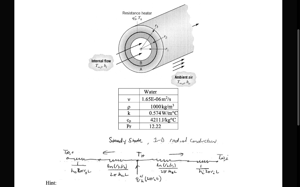
The total thermal resistance is the sum of the individual resistances in series:
We already know the conduction resistance formulas:
(We will cover the convection resistance terms, , in a later module.)
If one of the layers involves heat generation, the problem becomes more complex. You cannot simply use the resistance formula for that layer. Instead, you must solve the heat equation within that layer and use the interface conditions (equal temperature and equal heat flux) to connect it to the adjacent layers.
Let's look at a final, advanced example that combines heat generation with a composite structure. This is a very representative problem for your goal.
Read EXAMPLE 2–18 (Heat Conduction in a Two-Layer Medium). You don't need to re-check all the algebra. Instead, focus on the overall strategy: The problem is broken into two parts: the inner wire (with heat generation) and the outer ceramic layer (pure conduction). A solution is found for each part, both containing an unknown interface temperature, T_I. The crucial step: the heat flux -k rac{dT}{dr} is equated at the interface (r=r_1) for both solutions. This provides the equation needed to solve for the unknown T_I.
This strategy of "divide and conquer" by solving for each region and then stitching the solutions together at the interfaces using boundary conditions is a powerful technique for many advanced physics problems.
Conclusion
In this lesson, we moved from deriving formulas to applying them to solve practical and complex problems involving cylindrical and spherical geometries.
Key Takeaways:
- The temperature distribution in a hollow cylinder (no heat generation) is logarithmic, while in a hollow sphere it varies as .
- For a solid cylinder with uniform heat generation, the temperature profile is parabolic, with the maximum temperature at the center.
- The symmetry condition, at , is a critical boundary condition for problems involving solid cylinders or spheres.
- Complex, multi-layered problems can be solved by breaking the system into individual components, finding the temperature profile for each, and connecting them by enforcing that temperature and heat flux are continuous at the interfaces.
Preview of the Next Lesson:
In all our problems so far, we have assumed that thermal conductivity is a constant. In reality, can change with temperature. In our next lesson, we will tackle the learning outcome: Tackle problems with temperature-dependent thermal conductivity. This will modify our integration step, as will now be inside the integral with , but the fundamental principles of Fourier's law remain the same.