Hello! Welcome to your next lesson in the Embedded Interview Preparation Bootcamp.
In our last session, we navigated the complex world of the DMA controller, focusing on how it acts as an independent master to move data efficiently within an SoC. We covered its configuration via TCDs and tackled the critical system-level challenge of cache coherency.
Today, we shift our focus from a high-speed internal peripheral to a fundamental external interface you'll find on every microcontroller: the General-Purpose Input/Output (GPIO) pin. While seemingly simple, GPIOs are at the heart of the hardware-software boundary. Mastering their use in real-world scenarios, like handling imperfect inputs from mechanical switches, is a hallmark of a skilled embedded engineer.
Your learning outcome for this lesson is to: Implement a software debouncing algorithm for a GPIO input and compare it with hardware debouncing solutions.
1. The Problem: Why Ideal Switches Don't Exist in the Real World
In an ideal world, pressing a mechanical button would create a single, clean transition from a low voltage to a high one (or vice versa). In reality, the physical contacts inside the switch "bounce" against each other for a brief period before settling. A microcontroller, operating at millions of cycles per second, is fast enough to see these bounces as a rapid series of on-off-on signals from a single press.
This phenomenon is called switch bounce.
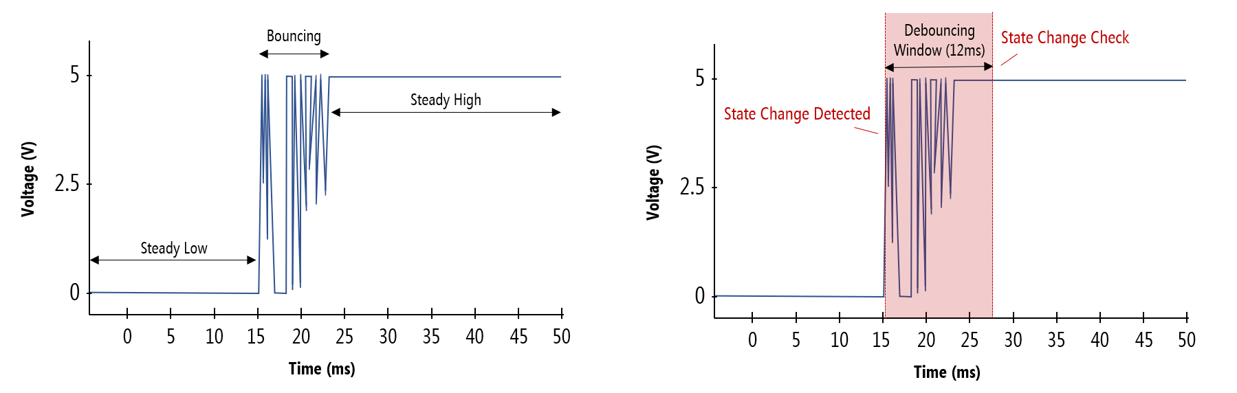
To see this problem in action, first watch this short, professional overview from Digi-Key, which uses an oscilloscope to visualize the bounce.
What is Switch Bounce and How to Debounce – ATM | Digi-Key Electronics
This video from DigiKey provides a concise explanation of switch bounce and its undesirable effects in a digital circuit.
Watch from the beginning to 01:12. Pay attention to the oscilloscope visualization and the explanation of why this bouncing is a problem for digital logic.
Now, let's see the practical effect this has on a simple program. The following segment shows what happens when a program tries to increment a counter on each button press without any debouncing logic.
Atmel Programming Tutorial 9 - Switch Debouncing
This segment from a tutorial by Chris Dahms demonstrates the real-world consequence of ignoring switch bounce.
Watch from 03:00 to 04:38. Notice how a single press causes the counter to jump by a large, unpredictable amount. This is a classic demonstration of the problem we need to solve.
As you can see, a single human action results in dozens of registered "presses," rendering the input useless. To be effective in an interview, it's also valuable to understand the deeper physics. Switch bounce isn't just about clean on/off transitions; it involves complex analog behavior.
For a truly expert-level understanding, it's worth reading Jack Ganssle's seminal paper, 'A Guide to Debouncing.' He conducted experiments on various switches and documented their real behavior.
Read the sections 'The Data' and 'Anatomy of a Bounce' (pages 2-9). You don't need to memorize the exact timings, but focus on these key takeaways for interviews: Bounce characteristics (duration, number of bounces) vary wildly between switch types and even between actuations of the same switch. The signal can linger in the 'illegal' voltage region between a logic 0 and a logic 1, causing 'virtual bounces' even if the contacts aren't physically bouncing. Some switches exhibit 'wiping' behavior, acting like a variable resistor before settling.
This deeper knowledge—that bouncing is a complex analog event, not just a simple digital flutter—is what separates a senior engineer from a junior one in an interview setting.
2. Hardware Debouncing Solutions
Before we dive into software, it's important to know that this problem can be solved entirely with external hardware components. The goal of a hardware debouncer is to filter out the noise and present a clean, bounce-free signal to the microcontroller's GPIO pin.
Common Hardware Techniques
-
SR Latch: For a single-pole, double-throw (SPDT) switch, two cross-coupled NAND or NOR gates can form a set-reset (SR) latch. The first contact bounce "sets" the latch, and any subsequent bounces on that contact have no effect. The latch only changes state when the switch makes contact with the other pole. This is a very robust solution but requires a more expensive SPDT switch.
-
RC Filter with Schmitt Trigger Inverter: This is the most common hardware solution for simple single-pole, single-throw (SPST) pushbuttons.
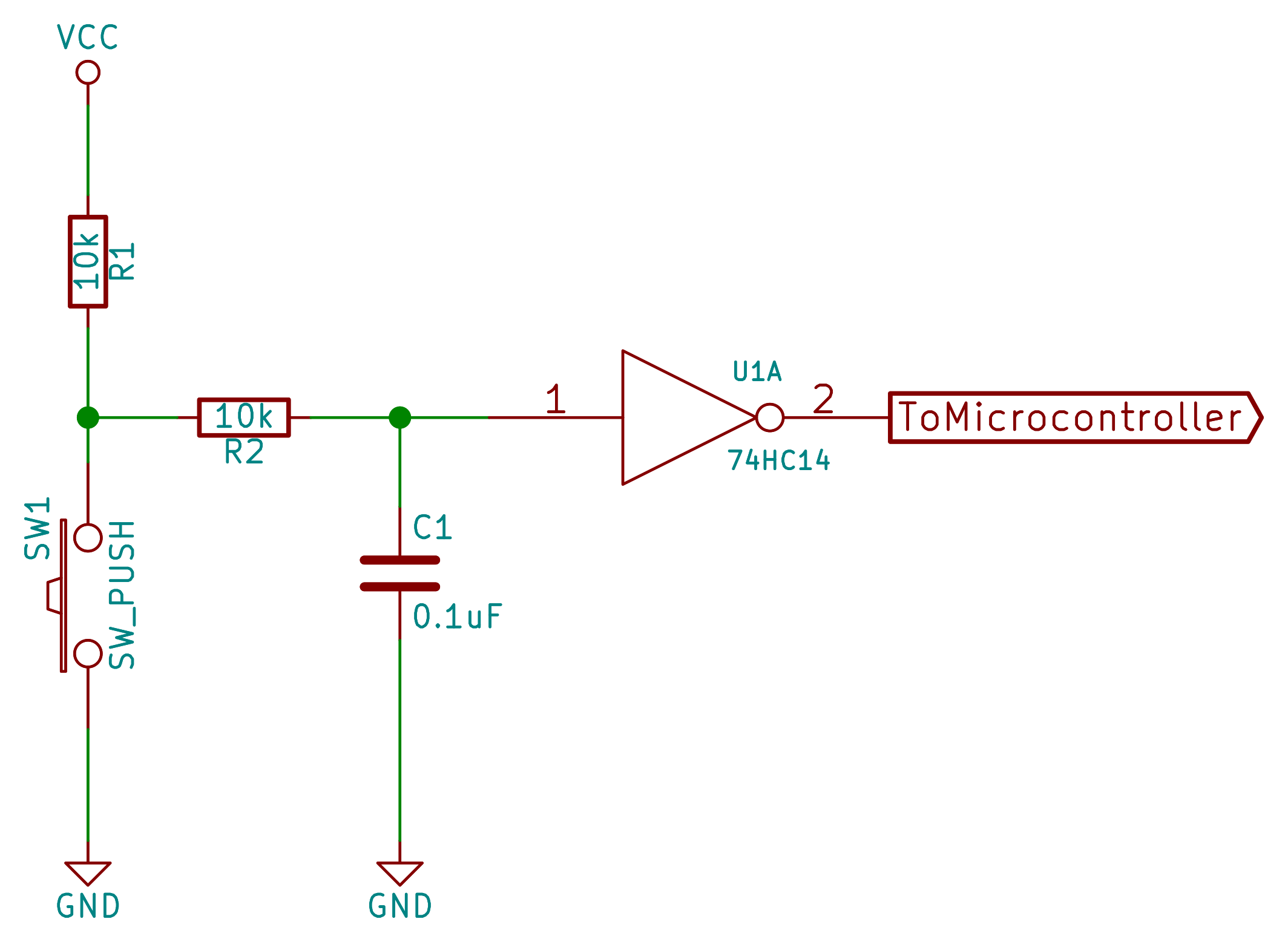
Here's how it works:
- When the switch is open, C1 is charged high through R1.
- When the switch is pressed, the contacts bounce. Instead of instantly going to ground, C1 begins to discharge through R2. The RC time constant is chosen to be longer than the bounce period, so the voltage across C1 drops slowly and smoothly.
- The Schmitt Trigger is essential. Unlike a standard logic gate, it has two different voltage thresholds for a rising edge (VT+) and a falling edge (VT-). This property, called hysteresis, prevents the output from oscillating as the capacitor voltage slowly crosses the logic threshold.
The following video provides a great overview of these hardware methods.
What is Switch Bounce and How to Debounce – ATM | Digi-Key Electronics
Let's return to the DigiKey video, which explains the common hardware solutions very clearly.
Watch from 01:23 to 03:11. This section covers the SR latch, the RC circuit (including a basic calculation), and the use of dedicated debouncing ICs.
The key takeaway is that hardware solutions offload the debouncing task from the CPU entirely, but at the cost of additional components, board space, and money (Bill of Materials cost).
3. Software Debouncing Algorithms
In most modern designs, debouncing is handled in software to reduce cost and component count. The goal is the same: to confirm that a switch's state is stable for a long enough period to be considered a valid press or release.
Here are three common algorithms, progressing from a naive approach to a professional, non-blocking solution.
Algorithm 1: The Blocking Delay (Naive Approach)
This is the simplest method and often the first one people learn.
- Read the GPIO pin.
- If it's in the "pressed" state, wait for a fixed delay (e.g., 20ms).
- Read the pin again.
- If it's still pressed, register the button press.
// Example of a blocking delay debounce
// NOTE: This is generally a bad practice in real systems.


#define DEBOUNCE_DELAY_MS 20

// Assume button is active-low
if (HAL_GPIO_ReadPin(BUTTON_PORT, BUTTON_PIN) == GPIO_PIN_RESET) {
    // Wait for the bounce period to pass
    HAL_Delay(DEBOUNCE_DELAY_MS);

    // Check the pin state again
    if (HAL_GPIO_ReadPin(BUTTON_PORT, BUTTON_PIN) == GPIO_PIN_RESET) {
        // Debounced press detected!
        // Toggle LED, etc.
        HAL_GPIO_TogglePin(LED_PORT, LED_PIN);

        // Wait for release to prevent multiple triggers
        while(HAL_GPIO_ReadPin(BUTTON_PORT, BUTTON_PIN) == GPIO_PIN_RESET);
    }
}
Why it's bad: The HAL_Delay() function is a blocking call. It wastes CPU cycles in an empty loop, preventing the processor from doing any other work. In any system with multiple tasks, an RTOS, or tight timing requirements, this approach is unacceptable.
Algorithm 2: Timer-Based Integration (A Robust Approach)
A much better approach is to use a periodic timer interrupt (like the SysTick in ARM Cortex-M cores) to sample the button at regular intervals (e.g., every 5ms).
The logic becomes an "integrator" or a "counter":
- In a periodic task, read the raw state of the switch.
- If the current raw state is different from the last known stable (debounced) state, start or increment a counter.
- If the raw state returns to the stable state, reset the counter.
- If the counter reaches a certain threshold (e.g., 4 consecutive identical readings, corresponding to 20ms if sampled every 5ms), the new state is considered stable. Update the debounced state and trigger the action.
The Ganssle PDF provides an excellent, time-based, and highly portable implementation of this concept.
Let's look at a professional implementation of a timer-based debouncer from the Ganssle guide. This is the kind of robust code you should aim to write.
Focus on 'Listing 1: A simple yet effective debounce algorithm' on page 19. Notice how it uses time-based constants (PRESS_MSEC, RELEASE_MSEC) rather than magic numbers for loop counts, making it maintainable and portable. The function DebounceSwitch1 is intended to be called from a periodic timer service.
This method is non-blocking and is the foundation of most professional debouncing routines.
Algorithm 3: The Bit-Shifting Integrator (An Elegant and Efficient Approach)
This is a very common and clever variation of the integration method, often asked about in interviews. It uses a single integer variable as a shift register to store the history of the switch's state.
The logic, called periodically from a timer task:
- Shift the history variable one bit to the left.
- Read the current raw state of the pin (0 or 1).
- OR the new state into the least significant bit of the history variable.
- After the initial fill, check if the history variable is all ones (e.g.,
0xFFFF) or all zeros (e.g.,0x0000). If so, a stable state has been detected.
This approach is extremely efficient as it involves only bitwise operations.
STM32 Button Debounce Code Examples [Tutorial]
This article from DeepBlueEmbedded provides a clean, modern C implementation of the bit-shifting technique for an STM32 microcontroller.
Read section '5. STM32 Button Debouncing (Bit-Shifting)' and the 'STM32 Button Debounce Code Example' that follows. Focus on the logic inside the BtnDebounce() function. This is a classic, highly efficient implementation perfect for an interview discussion.
Here's a simplified look at the core of the bit-shifting logic (for an active-low button):
bool BtnDebounce(void) {
    // History of the button states
    static uint16_t Btn_States = 0;

    // Shift history and read in the new state.
    // `!HAL_GPIO_ReadPin` makes a pressed state (0V) a logic '1'.
    Btn_States = (Btn_States << 1) | !HAL_GPIO_ReadPin(BUTTON_PORT, BUTTON_PIN);

    // Check for 12 consecutive '1's, indicating a stable press.
    // 0xFFF0 masks the upper 4 bits, which might not be filled yet.
    // If the check is true, a single press event is registered.
    if (Btn_States == 0xFFF0) {
        return true;
    }

    return false;
}
Conclusion: Comparing the Approaches
In an interview, you'll be expected to not only implement a solution but also to justify your choice by comparing the trade-offs.
| Feature | Hardware Debouncing (RC + Schmitt) | Software Debouncing (Timer-based) |
|---|---|---|
| CPU Overhead | None | Minimal (a few instructions per timer tick) |
| BOM Cost | High (resistors, capacitor, IC) | None (uses existing microcontroller resources) |
| Board Space | High (physical components) | None |
| Flexibility | Low (debounce time fixed by R, C) | High (debounce time is a software constant, easily changed/tuned) |
| Signal Integrity | Excellent (clean signal to MCU pin) | Depends on implementation; MCU pin still sees the raw, noisy signal. |
| Best Use Case | Safety-critical systems where software cannot be trusted, or if CPU resources are extremely constrained. | The vast majority of modern embedded systems. Cost-effective and flexible. |
Key Takeaways:
- Switch bounce is a physical phenomenon where mechanical switch contacts rebound, creating a noisy electrical signal that fast microcontrollers misinterpret as multiple presses.
- Hardware solutions, like an RC filter with a Schmitt Trigger, fix the problem at the source but add cost and complexity to the board.
- Software solutions are more common and flexible. Naive blocking delays are unacceptable in real systems.
- Professional software debouncing is non-blocking and typically uses a periodic timer to sample the input and "integrate" the state over time until it's stable.
- The bit-shifting algorithm is a highly efficient and elegant implementation of the software integration method and is excellent to have in your interview toolkit.
Preview of the Next Lesson:
We've just seen how to handle an unreliable input. But what happens if your entire program becomes unresponsive? In our next lesson, we will explore a fundamental system-level safety mechanism. Your learning outcome will be to: Explain the purpose of a watchdog timer and differentiate between a standard watchdog and a windowed watchdog.