Hello! Welcome to your next lesson in the RTOS fundamentals module.
In our last session, we established a robust framework for scheduling real-time tasks using Rate Monotonic Scheduling. We saw how a high-priority task can preempt a lower-priority one to meet its deadline. This preemption is the cornerstone of multitasking, but it raises a fundamental question: what exactly happens at the processor level when one task is forcibly paused and another begins to run?
Today, we will dissect this process. Your learning outcome is to: Explain the mechanics of a context switch, detailing what processor state is saved and how the stack frame is managed.
This is a critical topic for any senior embedded role, especially in semiconductor companies, as it demonstrates a deep understanding of the interplay between software (the RTOS) and hardware (the CPU). We will explore this on the ARM Cortex-M architecture, the de-facto standard for modern embedded systems.
1. The Problem: Saving and Restoring a Task's "Mind"
Before we dive into the hardware specifics, let's build a strong conceptual model. A running task's entire state of execution—its "mind," so to speak—is contained within the CPU's registers at any given moment. To switch tasks, the OS must save the current task's state to memory and load the state of the next task from memory.
But how can an OS save the state of a task that is currently running? The very act of saving the state would seem to alter it. This is a classic chicken-and-egg problem that cannot be solved by software alone.
The following video provides an excellent high-level overview of why hardware assistance is essential for this process.
How Hardware Assist Software When Multitasking
This video from the Core Dumped channel explains the fundamental challenge of a context switch and introduces the two main hardware-assisted approaches to solving it.
Watch the video from the beginning to 05:13 and then from 10:03 to 11:29. Focus on understanding: Why it's impossible for software alone to save its entire context, especially the Program Counter (PC). The concept of the CPU automatically pushing critical registers (like PC and Stack Pointer) onto a stack before jumping to an interrupt handler. This is the mechanism used by ARM Cortex-M.
2. Processor State on the ARM Cortex-M
As the video explained, the "context" is the set of CPU registers. On an ARM Cortex-M processor, this context can be broken down into three main groups. A deep understanding of these registers is fundamental.
ARM Cortex-M RTOS Context Switching
This article from Memfault's Interrupt blog is an excellent, practical guide to context switching on Cortex-M. We will use it as our primary reference. Let's start by defining the processor state we need to save.
Read the section 'Cortex-M ARM MCU Features'. Pay close attention to the subsections on 'Core Registers', 'Floating Point (FP) registers', and 'Special Registers'. You don't need to memorize every register, but you should be able to categorize them and understand their roles, especially: Callee-saved registers (r4-r11): These must be preserved by a function (or in our case, the context switcher). Caller-saved / scratch registers (r0-r3, r12): The calling function is responsible for saving these if needed. Key special registers: PC, LR, SP, and the CONTROL register which manages privilege levels and stack selection.
To summarize the key takeaways from that reading:
- Core Registers: General-purpose registers
r0-r12, Stack Pointer (SP, r13), Link Register (LR, r14), and Program Counter (PC, r15). - Special Registers: These control the processor's state. The
xPSR(Program Status Register) holds flags, theCONTROLregister selects the stack pointer, andPRIMASK/BASEPRImanage interrupt masking. - Stack Pointers: The Cortex-M has two stack pointers. The Main Stack Pointer (MSP) is used by the OS kernel and exception handlers. The Process Stack Pointer (PSP) is typically used by user tasks. This provides a crucial layer of separation and protection.
- Floating-Point Registers: If an FPU is present (like in Cortex-M4F or M7F), there's an additional set of registers (
s0-s31andFPSCR) that are part of the context.
3. The Context Switch Mechanism: An Orchestrated Dance
A context switch is a dance between hardware and software, typically orchestrated within a special interrupt handler. On ARM Cortex-M, this is almost universally done in the PendSV (Pendable Service Call) exception.
Here's the sequence of events:
- The Trigger: An event occurs that requires a context switch. Often, this is the
SysTicktimer interrupt, which an RTOS uses for time-slicing. The SysTick handler runs, calls the scheduler, and if the scheduler decides a higher-priority task should run, it pends the PendSV interrupt. - The Exception Entry (Hardware): When the PendSV interrupt is taken, the CPU hardware automatically performs the first part of the context save. It pushes a basic stack frame containing 8 registers (
r0-r3,r12,LR,PC,xPSR) onto the current task's stack (the PSP). - The Context Save (Software): The
PendSV_Handlerbegins to execute. Its job is to save the rest of the context. It pushes the remaining callee-saved registers (r4-r11) onto the same stack (the PSP). - Saving the Stack Pointer: The handler reads the final value of the PSP and saves it into the current task's Task Control Block (TCB), a data structure the RTOS uses to store all information about a task.
- Restoring the Next Context: The handler gets the TCB of the next task to run, retrieves its saved stack pointer, and loads it into the PSP.
- The Context Restore (Software): The handler pops the callee-saved registers (
r4-r11) from the new task's stack. - The Exception Exit (Hardware): The handler executes a special return instruction (
BX LR) using a magicEXC_RETURNvalue that was placed in the Link Register upon exception entry. This value tells the processor to:- Un-stack the basic frame (
r0-r3,r12, etc.) from the PSP. - Resume execution at the new task's saved Program Counter.
- Un-stack the basic frame (
This diagram provides a great visual summary of the process.
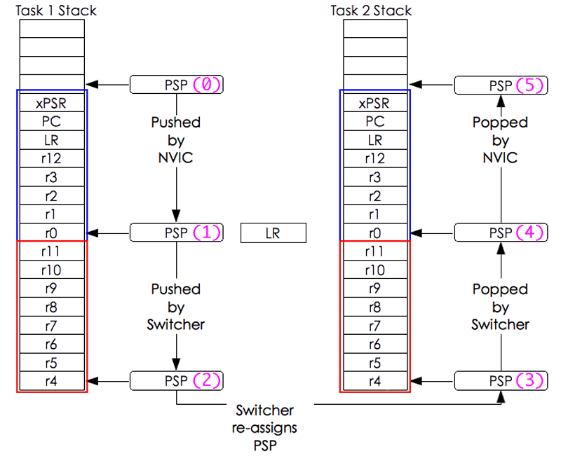
Now, let's see how this is implemented in practice. We'll look at it from two perspectives: building it from scratch and analyzing a real-world example in FreeRTOS.
Building the PendSV Handler
This video shows how to implement a PendSV_Handler in assembly, which is required for direct manipulation of the stack and core registers.
#23 RTOS Part-2: Automating the context switch
The Quantum Leaps channel provides a fantastic walkthrough of creating a context switch handler from the ground up. This will solidify your understanding of the assembly instructions involved.
Please watch these three segments: Why PendSV? (09:22 - 12:50): Understand why PendSV is the ideal interrupt for context switching and the importance of setting its priority to the lowest level. Structuring the Handler (17:36 - 22:24): See the C-based skeleton of the handler, which outlines the logic for saving and restoring context. The Assembly Implementation (24:25 - 29:40): This is the core segment. Observe how the C logic is translated into assembly using instructions like MRS (Move to Register from Special), PUSH/POP, STMDB/LDMIA, and how the stack pointer is manipulated.
Analyzing the FreeRTOS PendSV Handler
Now, let's cement this knowledge by stepping through the official FreeRTOS implementation using a debugger.
ARM Cortex-M RTOS Context Switching
Let's return to the Memfault article. This time, we will focus on the practical GDB walkthrough of the xPortPendSVHandler.
Read the section 'Demystifying the FreeRTOS Context Switcher', focusing specifically on the sub-section 'Context Switching'. Follow the GDB command-by-command analysis. This will show you: How to inspect the stack (x/a $psp) to see the hardware-saved frame. How mrs r0, psp gets the stack pointer. How stmdb and ldmia are used to save and restore the callee-saved registers. How the top-of-stack pointer is saved to and loaded from the pxCurrentTCB. The final bx r14 that triggers the hardware-assisted return to the new task.
4. The FPU Complication: Extended Stack Frames and Lazy Stacking
If your processor has a Floating-Point Unit (FPU), the context is larger. Saving and restoring an extra 33 registers (s0-s31 and FPSCR) on every single context switch would introduce significant overhead. The ARM architecture has a clever optimization for this called lazy stacking.
- Standard Behavior: When an exception occurs on a system with an FPU, the hardware saves an extended stack frame, which includes space for the basic registers and the FPU registers.
- Lazy Stacking Optimization: The hardware only reserves space for the FPU registers on the stack. It defers the actual saving of the FPU registers. Only if the interrupt handler itself executes an FPU instruction will the hardware pause, save the original task's FPU state into the reserved space, and then continue. If the ISR never uses the FPU, the expensive save/restore operation is skipped entirely, saving valuable cycles.
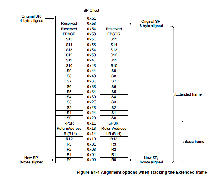
The FreeRTOS PendSV_Handler explicitly checks if the FPU was in use and needs saving:
" tst r14, #0x10 \n " // Test bit 4 of EXC_RETURN
" it eq \n "          // If result is zero (FPU was used)
" vstmdbeq r0!, {s16-s31} \n " // Save the other FPU regs
This is a key detail that top-tier interviewers look for, as it shows you've considered performance optimizations.
[PDF] Cortex-M4(F) Lazy Stacking and Context Switching
For a deeper dive, this ARM Application Note explains lazy stacking in detail. We won't read the whole document, but its diagrams and summary table are invaluable.
Please review the following parts of this document: Section 2: Lazy stacking feature (Page 7): Read this section to understand the logic behind LSPEN and ASPEN bits in the FPCCR. Section 3: Example lazy stacking scenarios (Pages 9-13): Study Figures 2, 3, and 4. These diagrams visually explain the difference in stack management when the FPU is used by the main task, the ISR, or neither. Section 5.2: Comparison of the two approaches (Page 24): Quickly review Table 3, which summarizes the pros and cons of always saving the FPU context versus using the lazy stacking scheme.
Conclusion
You now have a detailed, low-level understanding of one of the most fundamental RTOS operations. In an interview, being able to articulate this process with precision will set you apart.
Key Takeaways:
- A context switch is a hardware-software collaboration, initiated by an OS scheduler and executed in a low-priority interrupt handler like
PendSV. - What is saved: The entire processor context, including general-purpose registers (
r0-r15), special registers (xPSR), and FPU registers if applicable. - How it's managed:
- Hardware automatically saves a basic frame (
r0-r3, r12, LR, PC, xPSR) on exception entry. - Software (in
PendSV_Handler) manually saves the remaining callee-saved registers (r4-r11and FPU registerss16-s31). - The stack pointer is managed using the
PSPfor tasks andMSPfor the kernel/exceptions. The final PSP value is stored in the task's TCB. - A special
EXC_RETURNvalue inLRorchestrates the hardware-assisted return to the new context.
- Hardware automatically saves a basic frame (
- Advanced Topic (FPU): Lazy stacking is a key performance optimization that avoids unnecessarily saving the FPU context, reducing interrupt latency.
Preview of the Next Lesson:
Now that we know how the RTOS switches between tasks, a new problem emerges: what happens when two tasks need to access the same peripheral or piece of memory? If they are preempted at the wrong time, data can be corrupted. In our next lesson, we will tackle this challenge by exploring the essential tools for synchronization: mutexes, semaphores, and spinlocks.