Hello! Following our work on creating digital twins in the last lesson, we're now ready to map out how these entities will move and interact within the port's ecosystem.
In this lesson, you will translate a real-world logistics process into a formal, visual model. We will use Business Process Model and Notation (BPMN) 2.0, the global standard for process diagramming. Your goal is to model a container gate-in workflow using the Camunda Modeler. This bridges the gap between operational reality and technical implementation, a critical skill for a systems architect. We're moving from the data (what) to the process (how).
Why Model Processes with BPMN?
In any large-scale enterprise system, especially one involving multiple organizations and legacy systems like a port, clear communication is paramount. Misunderstandings between business stakeholders, operators, and developers lead to costly errors and delays. BPMN serves as a common language—a single source of truth—that turns complex operations into unambiguous visual models.
For an architect, a BPMN diagram is more than a flowchart. It is a precise blueprint for automation. It clarifies responsibilities, decision points, system handoffs, and potential bottlenecks before a single line of code is written for orchestration. Given your experience with audit-friendly workflows, you'll see how BPMN provides a clear, auditable trail of the process logic itself.
To start, let's get a high-level overview of BPMN's purpose and value from Camunda, the company behind the tools we'll be using.
BPMN Tutorial: Learn Business Process Model and Notation
This article from Camunda's official site introduces the core value proposition of BPMN. It explains why having a shared, visual language is essential for aligning business and IT teams.
Please read the first few sections of the page, from the beginning down to the end of the "What is BPMN?" section. Focus on the role of BPMN in creating a shared understanding and how it helps align teams on a process design.
The Core Building Blocks of BPMN
BPMN has a rich set of symbols, but you can model almost any process using just a few core elements. As we build our diagram, you will use these four main categories:
- Events: Circles that denote something that happens. They can start a process (thin border), occur during a process (double border), or end a process (thick border).
- Activities: Rounded rectangles that represent work to be done. A User Task (with a person icon) is performed by a human, often interacting with a system. A Service Task (with gears icon) is fully automated.
- Gateways: Diamonds that control the flow of the process. The most common are the Exclusive Gateway (XOR), which routes the flow down exactly one path, and the Parallel Gateway (AND), which splits the flow into multiple paths that all run concurrently.
- Pools and Lanes: Rectangles that organize activities. A Pool represents a major participant in a process (e.g., "Port Authority"). A Lane is a sub-partition within a pool, representing a specific role or department (e.g., "Gate Clerk").
This short video provides an excellent, practical demonstration of these elements, particularly the gateways, directly within the Camunda Modeler.
The Only BPMN Tutorial You Will Ever Need To Watch (For Beginners)
The "The Agile Business Analyst" channel provides a concise and practical introduction to the most important BPMN elements and demonstrates their use in Camunda.
Watch the following segments to see these concepts in action: Core Components Overview: A quick review of events, tasks, and gateways. Pools and Lanes: Understand how to represent different roles. Exclusive (XOR) Gateway: See a demonstration of an "either-or" decision. Parallel (AND) Gateway: Observe how to model tasks that run concurrently. Inclusive (OR) Gateway: A brief look at the more complex "one or more" gateway. We will primarily use XOR and AND, but it's good to be aware of this. Event-Based Gateway: Learn how a process can wait for different events.
Hands-On: Modeling the "Container Gate-In" Workflow
Now, let's apply this by modeling a simplified but realistic "Container Gate-In" process for Chittagong Port. Your task is to build this process diagram using the Camunda Modeler. If you haven't already, please download and install the Desktop Modeler.
We will model the interaction between the port and a truck arriving with a container. This involves multiple actors and system checks, making it a perfect candidate for a BPMN collaboration diagram.
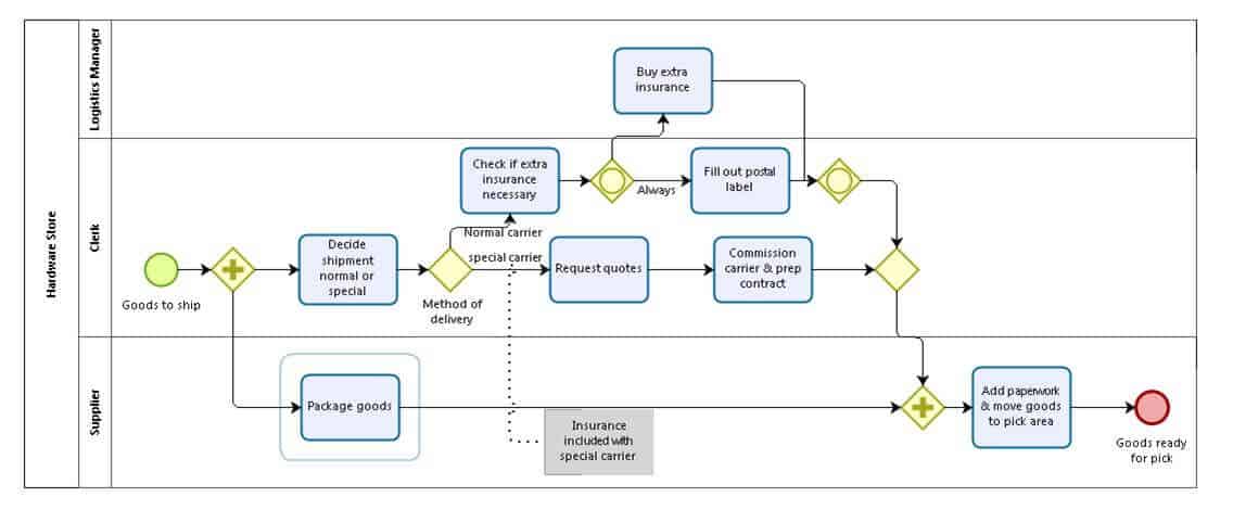
Process Specification:
Here is the workflow we will model. Create a new BPMN diagram in Camunda Modeler and follow these steps.
-
Define Participants (Pools and Lanes):
- Create a Pool named "Port Authority". This will contain the main process.
- Within this pool, create two Lanes: one for "Gate Clerk" (for manual/user tasks) and one for "Terminal Operating System (TOS)" (for automated/system tasks).
- Create a second, collapsed Pool named "Truck Driver" to represent the external participant interacting with our process.
-
Model the Process Flow:
- Start: The process begins when the truck arrives. In the "Truck Driver" pool, add a Start Event labeled "Container Arrives at Gate". Draw a Message Flow (a dashed line) from this event to a Message Start Event in the "Gate Clerk" lane labeled "Receive Arrival Notification".
- Verify Booking: The clerk must verify the container's booking details. In the "Gate Clerk" lane, add a User Task named "Verify Booking Information".
- System Check: The TOS validates the booking. In the "TOS" lane, add a Service Task named "Check Booking in Navis N4".
- Decision Point: We need to decide if the booking is valid. Add an Exclusive (XOR) Gateway after the service task. Name it "Booking Valid?".
- "No" Path (Invalid Booking):
- From the gateway, create a sequence flow labeled "No".
- Connect it to a User Task in the "Gate Clerk" lane named "Inform Driver of Issue".
- From there, draw a Message Flow to the "Truck Driver" pool, ending in a Message End Event named "Driver Notified".
- The main process path then goes to an End Event in the "Gate Clerk" lane named "Entry Denied".
- "Yes" Path (Valid Booking):
- From the gateway, create a sequence flow labeled "Yes".
- This splits into parallel activities. Add a Parallel (AND) Gateway.
- Path 1 (Clerk): Add a User Task in the "Gate Clerk" lane named "Inspect Container & Truck".
- Path 2 (System): Add a Service Task in the "TOS" lane named "Record Gate Entry Time".
- After both parallel tasks are complete, they must be synchronized. Add another Parallel (AND) Gateway to join the flows.
- After the join, add a final User Task in the "Gate Clerk" lane: "Print Gate Pass".
- Draw a Message Flow from this task to the "Truck Driver" pool, ending in a Message End Event labeled "Driver Receives Pass".
- Finally, the main process path goes to an End Event named "Gate-In Complete".
Validating Your Model with Token Simulation
One of the most powerful features of the Camunda Modeler, especially for someone with your technical background, is the built-in token simulation. It allows you to "execute" the diagram visually, watching a "token" move through the process. This is invaluable for debugging your logic, understanding how gateways operate, and demonstrating the process flow to stakeholders.

After you've built your diagram, enable token simulation and step through it. Test both the "Yes" and "No" paths at the decision gateway to ensure the logic flows as you expect. This hands-on validation reinforces the concept of the diagram as an executable model.
Conclusion
In this lesson, you've moved from abstract data models to a concrete, visual representation of a business process. You've learned the fundamentals of BPMN 2.0 and used the Camunda Modeler to create a diagram for a key port logistics workflow. This model serves as a vital communication tool and, as we'll see, the foundation for our orchestration logic. You now have a clear, standards-based blueprint that precisely defines the sequence of tasks, decisions, and responsibilities for the container gate-in process.
In our next lesson, we will begin to bring this static model to life. You will learn to use SimPy, a Python library for discrete-event simulation, to model dynamic port activities like random truck arrivals and queuing at the gate. These simulated events will eventually be used to trigger and drive the BPMN workflow we have just designed.