Hello! Welcome to our first lesson on the LLC Resonant Converter.
In our previous lessons, we analyzed the Phase-Shifted Full-Bridge (PSFB) converter and uncovered some of its inherent limitations. We saw that achieving Zero Voltage Switching (ZVS) on the lagging leg was relatively straightforward, but the leading leg struggled, especially at light loads. We also discussed the significant efficiency penalty caused by circulating currents during the freewheeling phase.
Today, we'll introduce a topology designed to overcome these specific drawbacks. The LLC resonant converter is one of the most popular and efficient topologies for modern power supplies. Our goal for this lesson is to explain the structure of an LLC resonant converter and how its resonant tank enables ZVS across a wide load range. By the end, you'll understand why this topology is so effective where the PSFB falls short.
The Anatomy of an LLC Converter
At first glance, an LLC converter looks similar to other isolated converters. It has a primary-side switching stage, a transformer for isolation, and a secondary-side rectification stage. The magic, however, lies in the "resonant tank" placed between the switches and the transformer.
Let's start by looking at the fundamental building blocks.
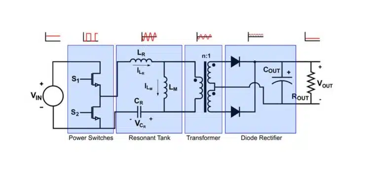
As Figure 1 shows, the converter has four main parts:
- Power Switches: This is an inverter stage, typically a half-bridge (two switches) or a full-bridge (four switches), that converts the DC input voltage into a high-frequency square wave. Your familiarity with Buck and Boost converters means you're already comfortable with this concept of a switching leg.
- Resonant Tank: This is the core of the converter. It takes the square wave from the switches and, through resonance, filters it into a sinusoidal current. This tank is composed of three elements: a series resonant inductor (), a series resonant capacitor (), and the transformer's magnetizing inductor (). The name "LLC" comes from these three components (, , ).
- Transformer: Provides galvanic isolation and steps the voltage up or down.
- Diode Rectifier: Converts the AC from the transformer's secondary back into DC for the output. A key advantage of the LLC topology is that it does not require a separate, bulky output inductor like those found in Buck, Boost, or PSFB converters.
To get a more detailed look at these components, let's turn to a great introductory article.
LLC Resonant Converter Design and Calculation
The article 'LLC Resonant Converter Design and Calculation' provides a clear, high-level overview of the converter's structure. We'll read the initial sections to solidify our understanding of the building blocks.
Please read the 'Introduction' and 'Power Switches' sections. Pay attention to the role of each block and the trade-offs between half-bridge and full-bridge topologies, which is a practical consideration in PCB reviews.
As the reading highlights, half-bridge configurations are common for lower power (under 1kW), while full-bridge is preferred for higher power. This is a practical rule of thumb you can use when evaluating schematics.
The Heart of the Matter: A Multi-Talented Resonant Tank
The genius of the LLC converter lies in how its resonant tank behaves under different load conditions. This is what allows it to maintain high efficiency from full load all the way down to no load.
The tank effectively has two different resonant modes depending on the load:
-
At Heavy Loads: The output load, when reflected across the transformer to the primary side, has a very low impedance. This low impedance essentially "shorts out" the magnetizing inductance (), preventing it from participating in the resonance. In this state, the tank behaves like a simple Series Resonant Converter (SRC), with resonance determined only by the series inductor () and series capacitor ().
-
At Light Loads: As the load decreases, its reflected impedance increases. The magnetizing inductance () is no longer shorted out and begins to participate in the resonance. The tank's behavior now also incorporates the characteristics of a Parallel Resonant Converter (PRC), where resonance is determined by and .
This ability to transition between two modes is what gives the LLC converter its remarkable flexibility and wide operating range.
The following reading explains this dual-mode behavior and introduces the concept of two resonant frequencies, which we will explore further in the next lesson.
LLC Resonant Converter Design and Calculation
Let's return to the 'LLC Resonant Converter Design and Calculation' article to see how the two inductors work together.
Please read the section titled 'Resonant Tank'. Focus on the explanation and accompanying graphs (Figures 5 and 6) that show how the tank's gain response changes based on which inductor is dominant.
How the Tank Delivers Wide-Range ZVS
Now we can connect the tank's operation to achieving ZVS. In a PSFB, we saw that achieving ZVS at light load was difficult because there wasn't enough energy in the primary current to discharge the switch capacitances. The solution was to increase the magnetizing current, but this came with the penalty of higher circulating losses.
In an LLC converter, the magnetizing current isn't a patch; it's a fundamental feature. The magnetizing current flowing through is what enables ZVS, and because it is largely independent of the load, ZVS can be achieved even with no load connected.
Let's walk through how this happens. The process is perfectly illustrated in the following video.
How does a Half bridge LLC Resonant Converter work? Half bridge LLC Resonant Converter Explained
The video 'How does a Half bridge LLC Resonant Converter work?' by Foolish Engineer provides excellent animations showing the current paths during a switching cycle.
Please watch the two segments from 03:52 to 05:36 and from 06:49 to 08:15. These clips show what happens during the dead time after each switch turns off. Focus on how the magnetizing current is responsible for discharging the parasitic capacitance of the next switch that is about to turn on, forcing its voltage to zero.
Let's summarize the key steps for achieving ZVS on switch Q2 (as shown in the first video clip):
- Q1 turns off: The dead time begins. Both switches are off.
- Magnetizing Current Finds a New Path: The current that was flowing through the magnetizing inductor () cannot stop instantly. It is redirected to charge the parasitic output capacitance () of Q1 and discharge the parasitic output capacitance of Q2.
- Vds of Q2 falls to zero: The magnetizing current successfully discharges Q2's capacitance, and its drain-source voltage () drops to zero.
- Body Diode Conducts: Once reaches zero, the current continues to flow, but now through Q2's intrinsic body diode. This clamps the voltage at (or near) zero.
- Q2 turns on with ZVS: The gate signal for Q2 is applied while its body diode is conducting. Since the voltage across the switch is already zero, it turns on with virtually no switching loss.
The exact same process occurs in reverse to achieve ZVS for Q1. Because this mechanism relies on the magnetizing current—which is always present—and not the load current, it works across the entire load range. As noted in the thesis "Chapter 4 LLC Resonant Converter" (resource LINK), "The ZVS is achieved with magnetizing current, which is not related to load current, so ZVS could be realized even with zero-load." This is the LLC's single biggest advantage over the PSFB.
Test your understanding!
A colleague is struggling to understand why an LLC converter can maintain ZVS at no load, while their PSFB design loses ZVS below 10% load. In one or two sentences, how would you explain the fundamental difference?
Show answer
You could explain that in an LLC converter, ZVS is achieved using the transformer's magnetizing current, which is an inherent part of the resonant tank and is present regardless of the output load. In a PSFB, ZVS relies on the load current, which disappears at light loads, causing the ZVS mechanism to fail.
Conclusion
In this lesson, we've dissected the LLC resonant converter and uncovered the secret to its high-efficiency operation. By moving beyond the trapezoidal currents of hard-switched converters and the limitations of the PSFB, the LLC uses a carefully designed resonant tank to create smooth, sinusoidal currents and ensure soft switching across a vast operating range.
Key Takeaways:
- An LLC converter consists of four main blocks: power switches, an LLC resonant tank (, , ), a transformer, and a rectifier. It notably lacks a separate output inductor.
- The resonant tank's unique structure allows it to behave like a series resonant converter at heavy loads and a parallel resonant converter at light loads.
- This dual-mode capability, combined with the inherent magnetizing current (), is the mechanism that enables ZVS across the entire load range, from full load down to no load. This overcomes the major drawbacks of the PSFB topology.
In our next lesson, we will dive deeper into the behavior of the resonant tank. We'll explore how designers use frequency modulation to control the converter's output voltage by manipulating its gain characteristics, and we'll introduce the critical concepts of resonant frequency and quality factor (Q).