Hello! In our last lesson, you took a significant step by implementing emissive materials, transforming ordinary objects into light sources. This allowed our renderer to produce beautiful, soft-lit scenes with emergent soft shadows—a hallmark of physically-based rendering.
Your ray_color function, which now looks something like emitted + attenuation * ray_color(...), is in fact a simple path tracer. It intuitively simulates how light bounces around a scene.
Today, we're going to dive into the "why." We will explore the formal mathematical theory that underpins all realistic image synthesis: the Rendering Equation. This learning outcome is crucial because it provides the foundational model of light transport. Understanding it will allow you to reason about why your path tracer works, how to debug it, and how to implement more advanced rendering techniques correctly. This equation is the theoretical core behind production renderers like Arnold and Karma.
1. Introducing the Rendering Equation
At its heart, the rendering equation is a mathematical statement that describes the "equilibrium" of light in a scene. It defines how much light, or more formally, radiance, leaves any given point on a surface in any given direction.
The core principle is elegantly simple:
Outgoing Light = Emitted Light + Reflected Light
A surface can generate its own light (if it's a light source), and it can reflect light that arrives from its surroundings. The rendering equation captures this with mathematical precision.
To get a quick and clear overview of its components, please watch this introductory video from NVIDIA.
Ray Tracing Essentials Part 6: The Rendering Equation
This video, 'Ray Tracing Essentials Part 6: The Rendering Equation', provides a concise breakdown of the equation's structure and terms.
Watch the entire video (it's short, under 4 minutes). Focus on how it breaks the complex-looking integral into three main parts: incoming light, the material, and a geometric factor.
Now, let's look at the equation itself and dissect it piece by piece.

A formal representation of the rendering equation, detailing each component. This equation is the cornerstone of physically-based rendering.
The equation is written as:
This might look intimidating, but it maps directly to our simple principle. Let's break it down using the excellent explanation from the "Introduction to the Rendering Equation" article.
Introduction to the Rendering Equation
This article provides a clear, mathematically sound explanation of the rendering equation's components. We will use it to understand each part of the formula.
Read the section 'The Rendering Equation'. Don't worry about the units and differentials for now. Focus on the conceptual breakdown of the left-hand side and the three terms inside the integral on the right-hand side.
Here is a summary of the key terms:
-
: This is the outgoing radiance from point in the direction . This is the quantity we want to compute—the "color" of a surface point as seen from a particular direction.
-
: This is the emitted radiance. It's the light that the surface at point emits on its own. For most objects, this is zero. For the light sources you created in the last lesson, this is a non-zero color.
-
: This integral represents the reflected radiance. It sums up all the light that comes in from every possible direction over the hemisphere above point , and determines how it reflects towards the viewer.
The three terms inside the integral are the heart of the light reflection model:
- : The Bidirectional Reflectance Distribution Function (BRDF).
- This function is the material. It defines how a surface reflects light. It answers the question: "For light coming in from direction , what fraction is scattered out in direction ?"
- A diffuse (Lambertian) material has a BRDF that scatters light equally in all directions. A metallic material has a BRDF that scatters light in a narrow, mirror-like lobe. Your
scatterfunction in thematerialclass is an implementation of this concept.
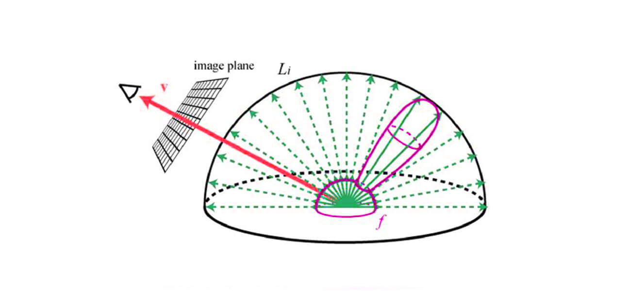
*This diagram visualizes the core of the rendering equation's integral: light arriving from many incoming directions ($L_i$) is reflected by the surface's material properties (the BRDF, $f$) toward the camera's view direction ($v$).*
2. : The incoming radiance.
- This represents the light arriving at point from direction . This is the crucial part that makes the equation recursive. The light arriving at our point is simply the outgoing light from some other point in the scene that lies in the direction . To find , we must solve the rendering equation for that other point! This recursive nature is exactly why we use ray tracing to solve it.
- : The cosine term.
- This term, also written as , accounts for the angle at which incoming light strikes the surface. As explained in the
geometrian.comarticle, light arriving at a shallow or grazing angle is spread over a larger surface area, so its contribution to the outgoing radiance is diminished. This is Lambert's cosine law, the same principle that makes the poles of the Earth colder than the equator.
- This term, also written as , accounts for the angle at which incoming light strikes the surface. As explained in the
2. Connecting the Equation to Your Code
The abstract math of the rendering equation directly maps to the ray_color function you've already written. Let's make that connection explicit:
- is the final
colorvalue that yourray_colorfunction returns. - is the
emittedcolor you get fromrec.mat_ptr->emitted(...). - is what you are approximating with the line
attenuation * ray_color(scattered, world, depth-1).
How is that one line of code an approximation of a complex integral?
- When you call your
scatterfunction, it generates a single scattered ray direction. This is like picking just one from the entire hemisphere . - The
attenuationcolor returned byscatteris a simplified combination of the BRDF and the cosine term . For a Lambertian material, the attenuation is constant, and the random scattering direction implicitly handles the cosine term. - The recursive call
ray_color(scattered, ...)is literally solving for , the incoming light from that one chosen direction.
So, your path tracer is solving the rendering equation by sampling one light path at a time and accumulating the result. This is a Monte Carlo approach, which we'll formalize in the next lesson.
Test your understanding!
In the rendering equation, if a material is a perfect mirror, what would you expect its BRDF, , to do? How does this relate to the scatter function for your metal material?
Show answer
A perfect mirror's BRDF would be zero for all incoming/outgoing direction pairs, except for the single pair that obeys the law of reflection (angle of incidence equals angle of reflection). It's essentially a delta function.
This is exactly what your metal material's scatter function does (when fuzz is zero). It doesn't pick a random direction; it calculates a single, deterministic reflection direction and returns true only for that path. All other potential light paths contribute nothing.
3. Global Illumination and Light Bounces
The rendering equation provides a powerful framework for thinking about light transport. One of the most elegant ways to view it is using operator notation, as shown in the presentation slides from TU Wien.
The equation can be written more compactly as:
Here, represents the light field of the entire scene, is the emitted light, and is a "transport operator" that describes one bounce of light. It takes the existing light field , propagates it through the scene, reflects it off surfaces, and gives you the result after one bounce.
By expanding this equation, we get a beautiful series:
This reveals exactly what your path tracer is simulating:
- : Light seen directly from a light source (0 bounces).
- : Light that has bounced once before reaching the eye (indirect illumination). This is what lights up the ceiling in a room with an upward-facing lamp.
- : Light that has bounced twice (secondary indirect illumination). This is responsible for subtle effects like color bleeding, where a red wall will cast a faint red tint on a nearby white wall.
- And so on for all subsequent bounces.
The sum of all these terms is called Global Illumination (GI). It's the "Holy Grail" of realistic rendering, and the rendering equation gives us the complete recipe for it.
The following video discusses this concept by splitting the rendering equation into practical components that renderers often compute separately.
Interactive Graphics 12 - The Rendering Equation
This video from Cem Yuksel's Interactive Graphics course provides a deep dive into the practical implications of the rendering equation, including the concepts of direct and indirect illumination.
Watch from 28:51 to 44:00. This section explains how the monolithic rendering equation is often split into 'direct illumination' (light from sources) and 'indirect illumination' (light from other objects). This is a critical concept in production rendering pipelines. The end of the segment also introduces the more general BSDF, which accounts for effects like refraction and subsurface scattering.
As the video explains, many renderers (especially real-time ones, but also offline renderers for optimization) treat direct and indirect light differently. Direct lighting can sometimes be computed more efficiently, while the multi-bounce indirect lighting is often the most computationally expensive part of rendering, responsible for the richest and most subtle visual effects.
Conclusion
Today, we've pulled back the curtain on path tracing to reveal the solid mathematical foundation it's built upon. You've learned that your renderer is, in fact, a solver for a fundamental equation of light transport.
Key Takeaways:
- The Rendering Equation is the formal basis for physically-based rendering, stating that Outgoing Light = Emitted Light + Reflected Light.
- The reflected light component is an integral over the hemisphere that accounts for all incoming light, modulated by the material's BRDF and the cosine of the incidence angle.
- The equation is recursive in nature, as incoming light to one point is outgoing light from another. This is why ray tracing is such a natural fit for solving it.
- Your
ray_colorfunction is a practical implementation that approximates the equation by tracing one path of light at a time. - Global Illumination is the complete solution to the equation, accounting for multiple bounces of light (direct and indirect), which are responsible for effects like soft shadows and color bleeding.
Next Steps
We've established that the rendering equation contains an integral and that your path tracer is approximating it by picking a random direction at each bounce. But is this approximation correct? How many samples do we need? And can we do better?
In the next lesson, we will formalize this process. You will learn how path tracing serves as a Monte Carlo method to solve the rendering equation. We'll explore the theory of Monte Carlo integration and see why our seemingly simple random-sampling approach converges to the physically correct solution.