Hello! Welcome back to our ray tracing journey.
In the last few lessons, we've assembled all the physics and mathematical tools needed to simulate light passing through transparent materials like glass and water. We've covered Snell's Law for refraction, derived the vector formulas, handled Total Internal Reflection, and, most recently, implemented Schlick's approximation to determine the varying probability of reflection versus refraction.
Today, we will consolidate all these components to achieve our learning outcome: to create a dielectric material class that handles both reflection and refraction. We will formalize the logic from our previous lessons into a clean C++ class, integrate it into our ray tracer, and, crucially, address a common but tricky bug that appears when tracing rays inside of objects. This step is fundamental to building a robust path tracer, mirroring the core principles used in production renderers like Arnold and Karma.
1. Consolidating Logic into a dielectric Class
So far, we have the key helper functions: reflect, refract, and schlick. Now it's time to package them into a new material class that inherits from our abstract material base class.
The structure will be straightforward:
- A class named
dielectric. - A constructor that accepts the material's index of refraction (e.g., 1.5 for glass).
- A member variable to store this
ref_idx. - An overridden
scattermethod that contains all the logic we developed in the previous lessons.
Let's look at the definitive implementation from our primary reference, Ray Tracing in One Weekend.
This chapter from Peter Shirley's book provides the complete, canonical implementation of the dielectric material. It's a great reference for seeing how all the pieces fit together into a final class.
Please read the section that presents the final C++ code for the dielectric class. It starts just after the explanation of Schlick's approximation. Focus on the class definition and the complete scatter method implementation.
The final scatter method integrates everything beautifully. Let's walk through the logic one more time to solidify our understanding. This code should look very familiar from our last lesson.
class dielectric : public material {
public:
    dielectric(double ri) : ref_idx(ri) {}

    virtual bool scatter(
        const ray& r_in, const hit_record& rec, vec3& attenuation, ray& scattered
    ) const {
        attenuation = vec3(1.0, 1.0, 1.0); // Glass absorbs no light, so attenuation is 1
        double etai_over_etat = rec.front_face ? (1.0 / ref_idx) : (ref_idx);

        vec3 unit_direction = unit_vector(r_in.direction());

        // Handle cosine calculation and check for Total Internal Reflection
        double cos_theta = fmin(dot(-unit_direction, rec.normal), 1.0);
        double sin_theta = sqrt(1.0 - cos_theta*cos_theta);

        if (etai_over_etat * sin_theta > 1.0 ) {
            // Total Internal Reflection: must reflect
            vec3 reflected = reflect(unit_direction, rec.normal);
            scattered = ray(rec.p, reflected);
            return true;
        }

        // Calculate Fresnel reflection probability using Schlick's approximation
        double reflect_prob = schlick(cos_theta, etai_over_etat);

        // Probabilistically choose between reflection and refraction
        if (random_double() < reflect_prob) {
            vec3 reflected = reflect(unit_direction, rec.normal);
            scattered = ray(rec.p, reflected);
            return true;
        }

        // If not reflected, then refract
        vec3 refracted = refract(unit_direction, rec.normal, etai_over_etat);
        scattered = ray(rec.p, refracted);
        return true;
    }

public:
    double ref_idx; // Index of Refraction
};
(Note: This version is slightly refactored from the book for clarity, but the logic is identical to what we've built).
This code is the culmination of our work on dielectrics. It correctly handles rays entering and exiting objects, accounts for TIR, and uses a physically-based probabilistic model for all other cases.

2. A Tale of Two Methods: Why Our Stochastic Approach is Better
You might wonder if there are other ways to handle a ray splitting into two paths (reflection and refraction). A common thought is to trace both rays. While possible, this can lead to an exponential explosion of rays, making the render very slow. Our method of picking just one path based on a probability is a cornerstone of path tracing.
It's reassuring to see even experienced developers arrive at this same conclusion.
Coding Adventure: Ray-Tracing Glass and Caustics
In this video, Sebastian Lague initially implements glass by using a stack to manage branching rays. However, he quickly discovers a more efficient method. Watching his thought process provides excellent validation for the stochastic approach we're using.
Please watch from 21:23 to 22:57. Notice his realization that a probabilistic choice (based on Fresnel) is simpler, faster, and produces better results than his initial, more complex recursive/stack-based approach.
As he concludes, the probabilistic method is "better in every way." It's faster, simpler to code, and more accurate because it doesn't have to discard low-energy light paths. This is a great example of how an elegant, physically-based algorithm often outperforms a more brute-force engineering approach in graphics.
3. The Hidden Bug: Handling Internal Intersections
Now that we have a material that can send rays through objects, we expose a subtle but critical bug that was lurking in our sphere::hit method.
Our original intersection code was written with the assumption that rays always start outside the sphere. It would calculate two intersection points (t0 and t1) and simply pick the smallest positive t value as the hit point.
Consider what happens now:
- A ray hits the front of a glass sphere. Our code correctly finds the hit point.
- Our new
dielectricmaterial computes a refracted ray that now originates inside the sphere. - We trace this new ray. It will intersect the sphere's surface at two points: one behind it (with a negative
tvalue) and one in front of it (the exit point, with a positivetvalue).
The problem is that our old logic might discard the intersection entirely if one of the t values is negative. We need to update our hit logic to correctly find the smallest positive t value, which represents the next valid intersection along the ray's path.
This kind of bug is common when adding new features, and debugging it is a core skill. Let's see how to fix it.
Ray tracing [C++ & SDL2] - Episode 10 - Refractive Materials
The QuantitativeBytes channel provides an excellent, detailed walkthrough of a ray tracer build. In this segment, the presenter discovers and fixes the exact sphere intersection bug we're discussing.
Watch from 49:20 to 53:28. The presenter explains why the original sphere intersection logic fails for rays inside the sphere and then walks through the corrected code, which properly tests both t1 and t2 to find the correct, positive intersection distance.
The key takeaway is that you can no longer make simple assumptions about intersections. The logic must be robust enough to handle all cases, including finding the valid exit point for a ray that starts inside an object.
Test your understanding!
Imagine our sphere::hit logic was simply if (t < 0) return false;. A refracted ray starts inside a sphere and travels towards the back surface. The quadratic formula gives two solutions for t: t0 = -5.0 (for the surface behind the ray's origin) and t1 = 2.0 (for the surface in front).
If our hit test function first checks t0, what would happen? How does the corrected logic fix this?
Show answer
If the function checks t0 = -5.0 first, it would see a negative value and immediately return false, incorrectly concluding that the ray doesn't hit the sphere. The ray would fly out into infinity, creating a black or incorrect patch in the rendered image where the back of the sphere should be.
The corrected logic fixes this by checking both t values. It would see t0 is invalid, but then check t1. Since t1 = 2.0 is positive, it would correctly identify this as the valid hit point, allowing the ray to exit the sphere properly.
4. Rendering with Dielectrics
With our dielectric class created and our intersection bug fixed, we can finally add glass objects to our scene. In your main function or scene setup, you can now instantiate the material and assign it to an object:
// In your scene setup...
auto material_glass = make_shared<dielectric>(1.5); // 1.5 is the refractive index for glass
add_object(make_shared<sphere>(point3(0, 0, -1), 0.5, material_glass));

// You can also make a hollow bubble by using a negative radius!
add_object(make_shared<sphere>(point3(0, 0, -1), -0.45, material_glass));
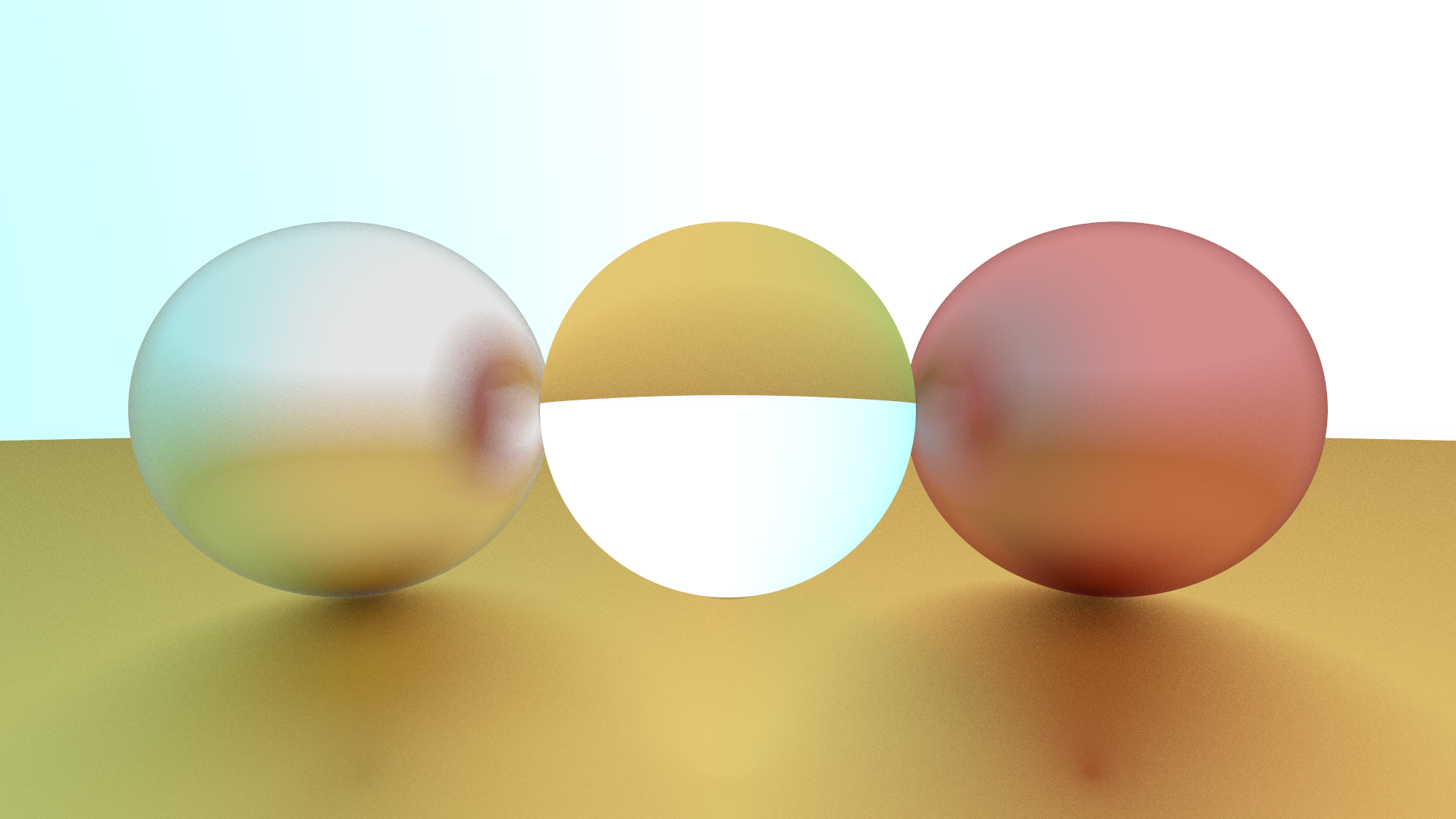
Running your renderer should now produce images with beautiful, physically-based glass spheres that both reflect and refract their environment.
Conclusion
This was a major milestone! We have successfully created a complete, robust dielectric material. You have not only implemented the complex interplay of reflection and refraction but also validated the efficiency of our approach and learned how to debug a non-obvious issue that arises from it.
Key Takeaways:
- A
dielectricmaterial class elegantly encapsulates the logic for refraction, reflection, and the probabilistic choice between them. - The stochastic path tracing method (randomly choosing one path) is more efficient and powerful than trying to trace all possible light paths.
- Adding new physical phenomena can reveal hidden bugs in older code. Robust intersection testing must account for rays originating inside objects.
- The final
scattermethod combines TIR and Schlick's approximation to decide whether a ray reflects or refracts, forming the basis for rendering all transparent materials.
Next Steps
We have mastered materials for simple spheres. However, the vast majority of 3D assets used in your field of VFX are not spheres; they are complex triangle meshes. In the next module, we will bridge this gap. We'll start by learning how to implement the Möller-Trumbore algorithm for efficient ray-triangle intersection, opening the door to rendering nearly any 3D model you can imagine.